J.P. Instruments Slim Line Gauges Installation Guide User Manual
Page 9
INSTALLING THE SLIM LINE® INSTRUMENT SERIES
PAGE 9 OF 14
REV
B
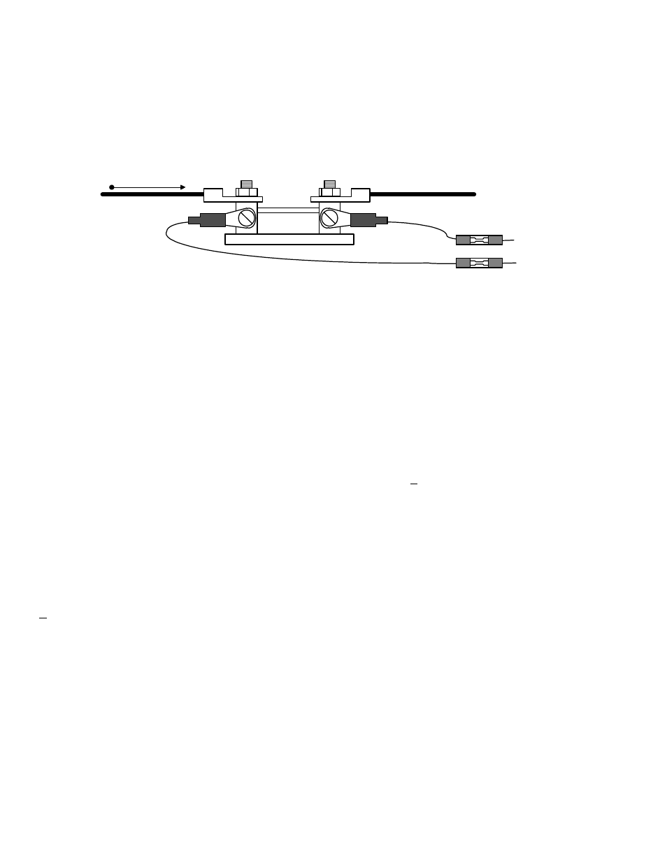
20) VOLT/AMP Shunt Wiring
Connect the white lead from the Slim Line instrument to the positive shunt terminal and the gray lead to the
negative shunt terminal. Optionally, you may install 1 amp fuses in series with the shunt sense wires. Do not
allow any other connection to the shunt. Do not power the Slim Line instrument from the shunt.
+
white +
gray -
1 amp optional fuse
2 plcs
SHUNT
direction of positive current flow
21) Oil Pressure, Fuel Pressure, Boom Pressure Sensor Wiring
If you have not already done so, install a ring-spade lug on each of the two pressure sensor terminals. Cut sensor
leads to length at the pressure sensor. Provide adequate service loop. Attach the supplied female spade lugs by
stripping and crimping a pin on each wire, and then inserting each pin onto the pressure sensor. There is no
polarity restriction on the two wires.
22) Specifications and Limitations
Environmental:
Passed TSO C43c
Power:
10 to 35 volts DC, 250 ma
Operating Temperature Range:
-40 to 195 °F
Display Size:
2.0 x 0.95 inches
Common Mode Range:
+ 4v, rejection > 80db
Analog-Thermocouples:
Resolution: 1.0 °F
Accuracy: + 1.0 °F
Calibration: K
Pressure Sensors:
Oil (0 to 150 psi)
Fuel (0 to 30 psi)
Boom (0 to 150 psi)
MP (0 to 40 psi)
Volt/amp:
Voltage 10-35 volts
Shunt 50 mv. at 60 amps or 100 amps