2) initial bench check, 3) installing the instrument – J.P. Instruments Slim Line Gauges Installation Guide User Manual
Page 2
INSTALLING THE SLIM LINE® INSTRUMENT SERIES
PAGE 2 OF 14
REV
B
J. P. INSTRUMENTS
PO Box 7033
Huntington Beach, CA 92615
2) Initial Bench Check
Connect the red wire to +12V or +24 V and the black wire to power return. Verify that the display lights up. If
the alarm limit has to be changed, it will be easier to do it now before the instrument is installed in the aircraft.
See the procedures near the end of this manual.
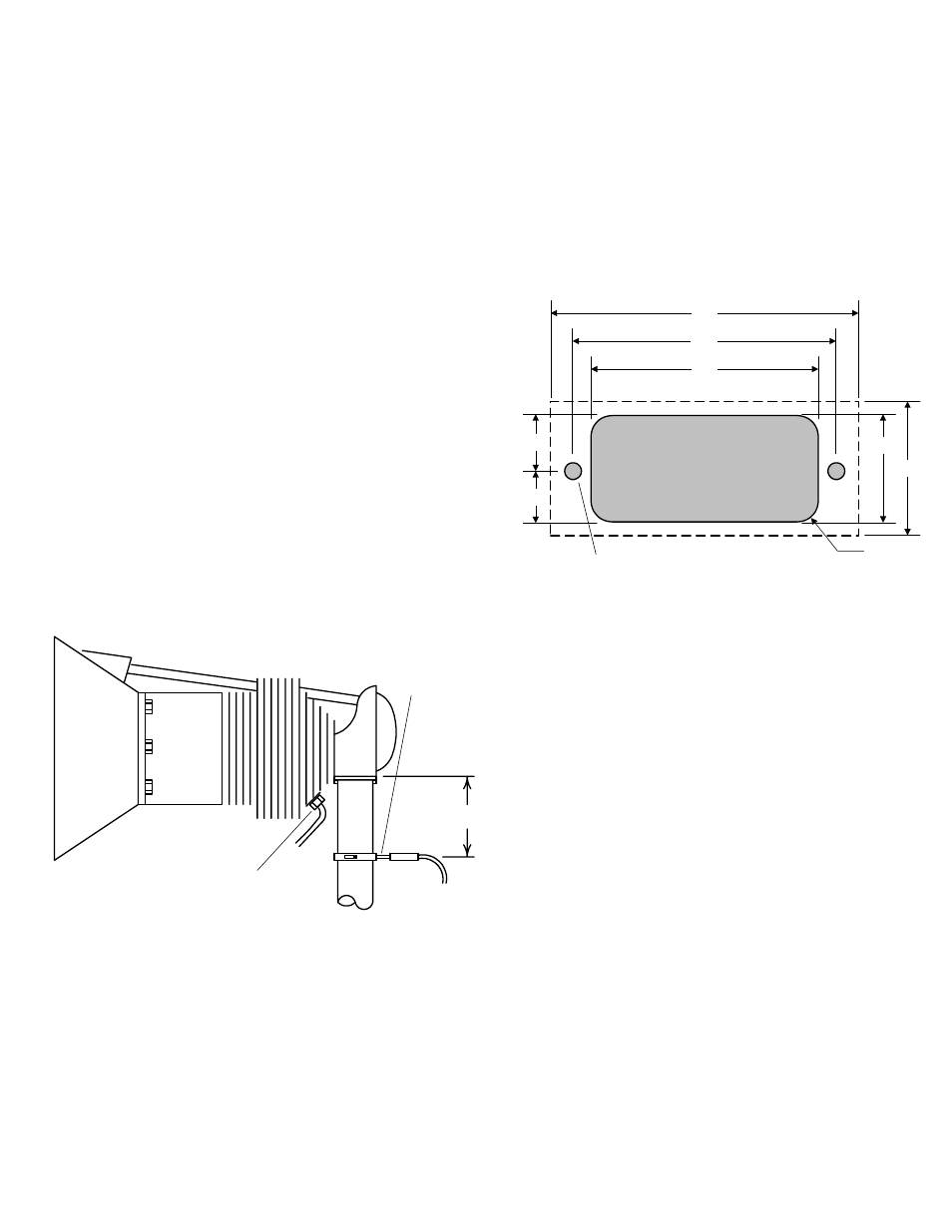
3) Installing the Instrument
Installation should be in accordance with Advisory Circular
AC43.13-1A. Identify the location for the instrument on the
instrument panel that can accommodate 2.75 inches wide by
1.2 inch high instrument, and 3.5 inches clearance behind
the instrument panel. Check the rear clearance with the
connectors attached to the instrument.
If more than one instrument is to be installed, the horizontal
center-to-center spacing must be at least 2.75 inches, and
the vertical center-to-center spacing must be at least 1.2
inches. Two instruments can be installed in a 3¼ inch hole.
Contact JPI for an optional bezel.
4) Exhaust Gas Temperature (EGT) Probe
Installation
Determine the locations of all holes before
drilling to ensure that nothing interferes with the
probe, clamp, clamp screw or wire. The model
M-111 EGT probe will fit any engine having
existing holes in the exhaust stack of between
0.125 in. and 0.250 in. If no hole exists, drill a
0.125 in. hole and ream to fit. For multi-EGT
probe installations, it is important that each probe
be mounted a uniform distance from the exhaust
stack flange. A nominal distance of 2 to 4 inches
from the exhaust flange is recommended. If the
recommended distance is impractical due to
obstructions, slip joints or bends in the exhaust
system, then position the probes a uniform
distance from the flange as space permits. Careful matching of probe position will provide the best temperature
readings. Do not mount EGT probes in slip joints.
Insert the probe in the exhaust stack hole such that the tip of the probe is in the center of the exhaust stream.
Tighten the stainless steel clamp and torque to 45 in/Lbs. Cut off excess strap close to the screw.
5) Turbine Inlet Temperature (TIT) Probe Installation
The standard TIT probe PN M111-T with a #48 clamp is placed in the exhaust stack accumulator to a maximum
depth of 1/2 inch and approximately 4 inches from the turbine inlet if possible, on the wastegate side of the
turbine.
2" to 4"
EGT probe
Drill no. 40
pilot hole,
then no. 30
hole.
CHT probe
exhaust stack
instrument panel cutout
2.35
2.03
0.46
R0.125
0.169 D 2 plcs
2.75
1.20
0.51
0.97 ref