GFB Short Shift Kit for MY97-07 WRX 5-speed (part 4001) User Manual
Page 3
7.
Smear a small amount of grease onto the shift stick ball. Thread the
supplied M12 x 1.25 hex nut onto the threaded gear knob end, until
the top of the stick is just a fraction lower than the top of the nut.
This nut is used to protect the thread of the stick for the next step.
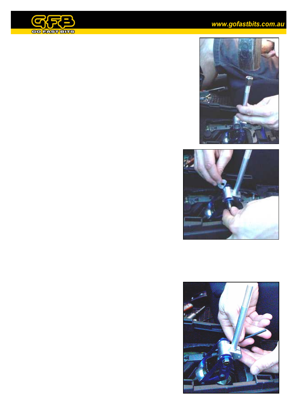
8.
Holding the stick upright, press the ball against the socket and strike
the top of the M12 nut with a hammer to pop the ball into the socket
(figure 6). This takes a solid blow to achieve, so the heavier the
hammer, the easier it will be (slow pressure simply does not work).
This process will not damage the ball or the cup, as the cup is
designed to spread apart for assembly. Make sure to remove the M12
nut before continuing.
Figure 6
9.
Slide the shift pivot onto the shift stick, then remove the urethane
bushes from the factory shift stick and insert them, along with
the suitable steel sleeve, into the GFB unit (NOTE: For
MY97-00 models, use the provided steel sleeve. For MY01-04
models, use the factory sleeve instead). DO NOT tighten the
screw to clamp the shift pivot to the stick just yet.
10.
Decide on how short you want the shift (pick one of the three
holes in the side plates, the higher the hole, the shorter the
shift), as a guide GFB recommends using the middle hole to
begin with. Line up the steel sleeve in the shift pivot with the
selected hole, then hold one of the M8 washers between the
sleeve and the side plate (NOTE: For MY97-00 models do not
use the washers, the sleeve is the correct length to fit between
the plates. It is not possible to use the lowest hole setting in
MY97-00 models).
Figure 7
Slide the M8 bolt (use the supplied one for MY97-00, the factory one for MY01-current) through the
side plate, the washer, and into the sleeve (figure 7). Then hold the remaining washer in the same place
on the other side, and push the bolt through fully. Thread the nut onto the end and tighten.
11.
Slide the shift pivot up and down until the factory linkage does
not hit the metal plate above it, or drag on the rubber boot
below, then re-tighten the screw firmly (figure 8). Do a final
check to ensure the linkage clears its surroundings in all gears.
12.
Replace the plastic shrouds in the reverse order of removal.
NOTE:
•
Always make sure that no part of the shift mechanism is contacting
any of the surroundings in all gears.
•
As the shift throw is reduced by a percentage, the principle of levers
means that the force required to shift gears is proportionally
increased. THIS DOES NOT MEAN IT WILL WEAR YOUR
GEARBOX! THE SHIFTER IS MERELY A LINKAGE TO
THE GEARBOX - DRIVER ABUSE IS THE ONLY THING
RESPONSIBLE FOR GEARBOX WEAR OR DAMAGE.
Figure 8