Hornady Lock-N-Load Control Panel User Manual
Page 7
7
NOTE:
If mounting on a Dillon
press, please contact Hornady at
1-800-338-3220 and request part
number 399274.
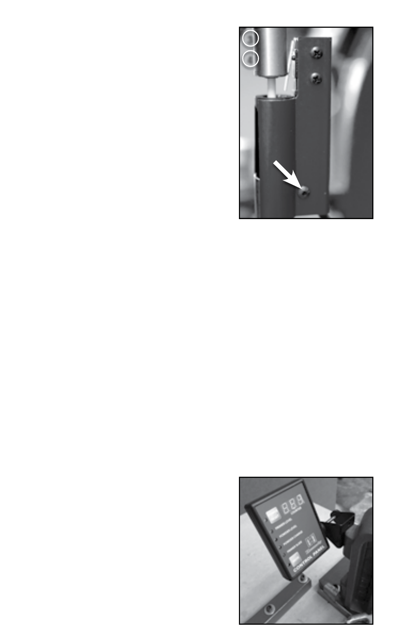
4) Lightly tighten the bracket down using
a
1
⁄
16
” hex wrench and a ¼” open end
wrench on the bottom 4-40 Screw and nut.
5) Adjust the Stop up or down on the
Primer Follower rod to the correct
level by sliding the o-rings on each
side of the stop up or down.
OPERATION
• When the level of primers become
low, the stop on the top of the Primer
Follower Rod should trip the sensor.
FAQ
WILL THE CONTROL PANEL FIT ON OTHER PRESSES?
• The Control Panel mounting bracket is designed to fi t onto a 1”
square tubing, however, it may be mounted onto other surfaces using
the through holes on the mounting bracket.
• The Counter and Primer Slide Sensor are not designed to fi t on
other presses.
• The Primer Level Check will fi t onto an RCBS primer tube. If the Primer
Level Check will be used on a Dillon press, please call Hornady Mfg.
at 1-800-338-3220 and request part number 399274.
• The Powder Level Check is designed to fi t on both a standard RCBS
and Dillon powder hopper.
• The Hornady Safeguard Die is designed to fi t on any press with a
7
⁄
8
”–14 thread.
CAN THE CONTROL PANEL BE MOUNTED
ONTO A LOCK-N-LOAD
®
AP
™
WITHOUT A
CASE FEEDER?
• Yes, Hornady recommends
attaching the Control Panel
using the through holes in the
mounting bracket, and Case Feeder
¼”–20 mounting holes on the back of
the Lock-N-Load
®
AP.
™
3
4