4 internal fm mode – BNC 630 User Manual
Page 22
17
5.4 Internal FM Mode
Introduction
The Internal FM mode generates a frequency modulated signal of fixed amplitude. An internally-generated sinusoid is used as a
modulating signal to vary the frequency of a carrier sinusoid.
Internal FM Mode Parameters
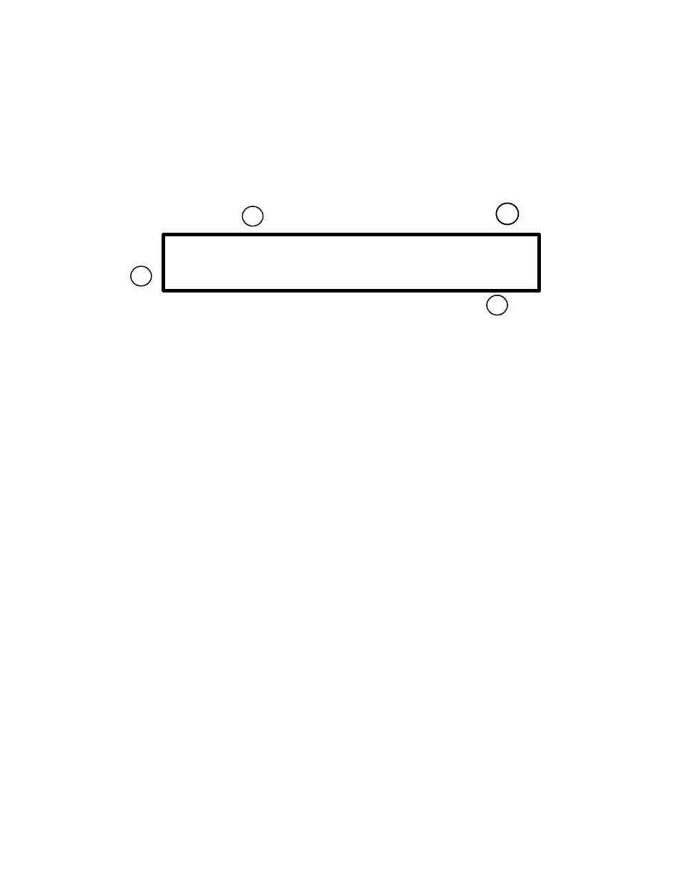
The Internal FM mode has the following front panel display:
Figure 5.4-1: Internal FM mode display
1. Modulating Frequency
In this field enter the frequency of the modulating sinusoid. You may enter from 0 Hz to 10,000 Hz in 1 Hz steps.
2. Peak Frequency Deviation
In this field specify the degree to which the modulating signal is allowed to change the carrier frequency. You may enter from 0 Hz
(no change) to 5.0 MHz in 1 Hz steps
This parameter is a peak value. If the deviation were 1 KHz and the carrier frequency were 1 MHz, for example, then the output
frequency will swing between a maximum of 1 MHz + 1 KHz and a minimum of 1 MHz - 1 KHz.
Note: If values for the deviation and carrier frequencies are entered such that the output frequency exceeds the 0 to 21.5 MHz
range, distortion of the output waveform may result.
3. Carrier Frequency
In this field enter the frequency of the carrier. You may enter from 0 Hz (DC) to 21.5000000 MHz in .01 Hz steps.
Note: If values for the deviation and carrier frequencies are entered such that the output frequency exceeds the 0 to 21.5 MHz
range, distortion of the output waveform may result.
4. Level
In this field enter the output level, from 4 mVp-p to 10 Vp-p in 1 mV steps or from -44.0 dBm to +24.0 dBm in .1 dBm steps.
NOTE: The level specified is a 50 ohm LOADED level. This is the level of the signal which will appear across a 50 ohm load
connected to the SIG Out connector. Into an open circuit, the output swing will be twice the value entered.
Offset
You can enter an offset voltage for the output waveform. For more information on output offsets refer to section 4.4.
Ext Gating Input
(rear panel connector)
This TTL compatible input can be used to gate the output signal on or off. A logic high voltage turns off the output.
For further information on the Ext Gating Input, refer to section 2.0.
Int FM: 1,000 Hz
Pk dev: 10,000 Hz
20,000,000.00 MHz
-10.0 dBm
2
1
3
4