Rubicon Express RE7364 User Manual
Page 7
RI73547364 Page 7 of 11
4.
After the Rubicon Express rear control arm brackets are installed the factory upper and lower rear
control arm brackets must be removed.
5.
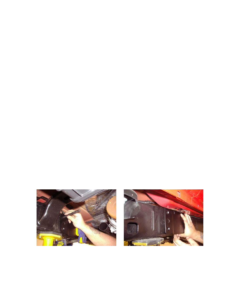
The front edge of the rear body mount must be trimmed 2” up for additional control arm clearance.
(photo )
CAUTION: During the next few steps we recommend constantly double checking the marked hole locations, pilot drill
locations and final drill locations. Doing so will result in a better fit without the need to ream holes for proper installation.
A. First, separate the four brackets (2 per side) that make up the left and right bracket sets. The brackets in the photo are
shown as left and right assemblies with the top of the photo being the front of the vehicle. (Photo 13)
B. Using the driver’s side inner reinforcement plate, locate the indexing oval on the inside of the driver frame rail. Mark the 2
countersunk holes at the rear of the bracket and 3 square holes. (photo 14) Drivers side shown
C. Using the same driver’s side inner reinforcement plate, repeat step B on the passenger outside frame rail with the addition of
marking the 3/16” hole near the bottom center of the plate. (photo 15) Passenger side shown
D. Using the passenger side inner reinforcement plate repeat steps B & C on the inside passenger and outside driver frame
rails.
E. Using a 1.5” hole saw, cut the relief hole for the outer control arm plate to sit flush against the outside frame rail.
(photo 16)
F. Locate the outer nut plate over the outside frame rail and double check the prior marked three square and two tapered
holes. If the alignment is good drill the remainder of the marked holes to 3/16”
G. On the inside of the frame us a 1” hole saw to open the two rear most vertically marked and pilot drilled holes for the ½”
I.D. threaded weld spacers. Drill all other holes to ½” thru both frame rails.
H. Place the outer nut plate on the outside frame rail. Using a spare ½” bolt, partially engage the threaded spacers on the bolt
and insert thru the inside of the frame. Insert the ½” tapered head bolt thru the nut plate and into the spacer from the
outside frame rail, tighten to secure and remove the spare bolt from the spacer. Weld each spacer to the inside of the frame
rail, sand the frame smooth and paint all raw steel. (Photo 17)
NOTE: When welding the spacers to the inside frame rail it may be helpful to leave the spare bolt in the spacer to prevent the
weld berries from entering and damaging the threaded spacer.
I.
Place the inner reinforcement plate on the inside frame rail and insert the three ½” carriage bolts thru all three brackets.
Install the two ½” tapered head bolts from the inside to the threaded spacers and tighten. (photo 18) Passenger inside
J.
Using washers and nylock nuts, tighten the three carriage and four tapered head bolts to 55 ft/lbs. (photo 19)
K. Mark the two tapered holes on the bottom of the frame rail and drill to ½”. Using a piece of mechanics wire, insert the nut
strip thru the existing hole in the outside frame rail and pull into location. (Photo 20) Drivers side
L. Install one of the tapered head bolts into the open hole, pull the wire from the nut strip and install the second tapered head
bolt. Torque to 55 ft/lbs. (photo 21)
Photo # 14
Photo # 15