Rubicon Express RE7364 User Manual
Page 4
RI73547364 Page 4 of 11
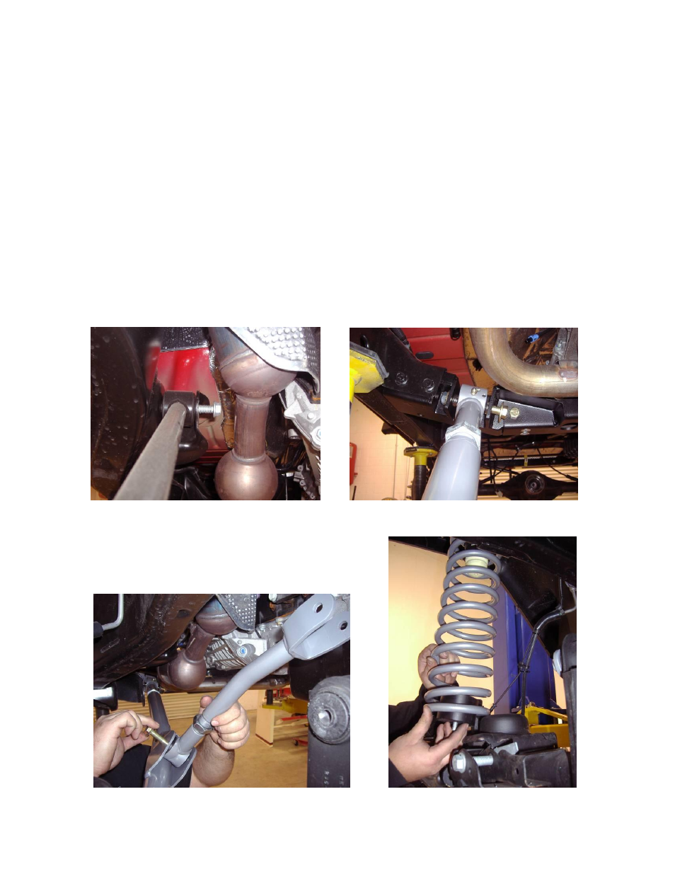
The upper front arms are symmetrical and can be used on either the left or right side. (photo 6) Passenger side
shown.
C. Using the supplied 9/16” x 4.5” bolt from the Rubicon Express front arm kit, install the passenger side lower arm into the cross
member mount. (photo 5) Next install the bushing end of the arm into the stock lower control arm location on the axle housing
using the factory hardware.
D. Set the upper arms to 15 1/8” center to center. With the supplied ½” bolt install the rubber bushing end into the pocket on the
lower control arm and the fork of the arm over the bushing mount on the axle. Use the factory hardware thru the fork end of the
arm. (photo 6) If it is necessary to have the upper arm shorter for more castor adjustment the male portion of the threads on
the control arm can be cut down the necessary amount. Be sure that there is always 1” of thread engagement between the
coupler and control arm.
NOTE:
The rubber coupler is welded at an offset angle. Be sure when installing the arm that the bushing is in a neutral
position. If the arm does not drop over the upper mount remove the ½” bolt and rotate the coupler 180 degrees.
E. Repeat steps A – D on the drivers side
F. Tighten the lower control arm bolts at the cross member only, all other rubber attaching points should remain loose until the
vehicle is under its own weight to prevent bushing preload.
Photo # 4
Photo # 5
Photo # 6
Photo # 7