Thermocouple – L.B. White I-17 Infraconic User Manual
Page 18
18
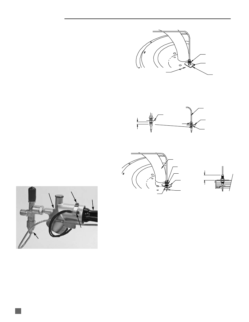
LEAD END OF THERMOCOUPLE
THERMOFUSE
5/16"
COVER
UPPER NUT
THERMOCOUPLE
LEAD
COVER
LOWER NUT
THERMOCOUPLE INSTALLED
UPPER RETAINING NUT
KEY HOLE SLOT
COVER
THERMOCOUPLE INSTALLED
INJECTOR TUBE
THERMOCOUPLE BODY
RETAINING NUT
COVER
THERMOCOUPLE TIP
LOCATION HOLE IN PLATE
1/2 IN TO 9/16 IN
FINISHED
THERMOCOUPLE
POSITION
1. Loosen the thermocouple connector nut at the safety
control valve. See Fig. 23.
2. L o o s e n t h e s c r ew s e c u r i n g t h e c l i p h o l d i n g t h e
thermocouple’s auto reset temperature switch to the air
housing. See Fig. 23.
3. Loosen upper retaining nut on thermocouple.
See Fig. 24.
4. Remove the thermocouple, with nuts and cover, from the
heater.
5. Position the thermocouple cover and nuts onto the
replacement thermocouple as shown in Fig. 25 Use the
cover from the original thermocouple and the nuts
supplied with the replacement.
6. Angle the thermocouple slightly so its tip and lower nut
pass through the keyhole slot. The tip must be located
within the thermocouple location hole of the burner plate.
Pull up on the thermocouple lead so the lower nut is tight
against the inside of the heater housing. Tighten upper
nut against the cover and housing. See Fig. 26.
7. The installed finished position of the thermocouple is 1/2
to 9/16 inch from the top edge of thermocouple to the
heater housing. See Fig. 26.
8. Thread the nut on thermocouple into gas control valve.
Tighten finger tight and snug in place. Position the
thermocouple’s auto reset switch under the retaining clip
and tighten the screw. See Fig.23.
FIG. 23
FIG. 24
FIG. 25
FIG. 26
TESTING THE THERMOCOUPLE
The thermocouple includes an auto reset temperature
activated switch. See Fig.23. The switch will open the
thermocouple circuit and shut off the safety valve if the
temperature at the air housing increases abnormally. To
test the thermocouple proceed as follows:
-- Remove the thermocouple from the heater
. -- Connect an ohm meter between the thermocouple
contact nut and tip.
-- A reading of less than 1 ohm is acceptable. A reading
showing overload or infinite resistance indicates an
open auto reset.
-- If open, allow the thermocouple to cool for 5 minutes.
Retest the thermocouple. If the reading is not 1 ohm or
less, replace the thermocouple.
THERMOCOUPLE
VENTURI TUBE
VENTURI TUBE
AIR HOUSING
RETAINING CLIP AND SCREW
LOOSEN THERMOCOUPLE NUT
AUTO RESET
TEMPERATURE
SWITCH