Bypass orifice, Safety gas control valve – L.B. White I-17 Infraconic User Manual
Page 15
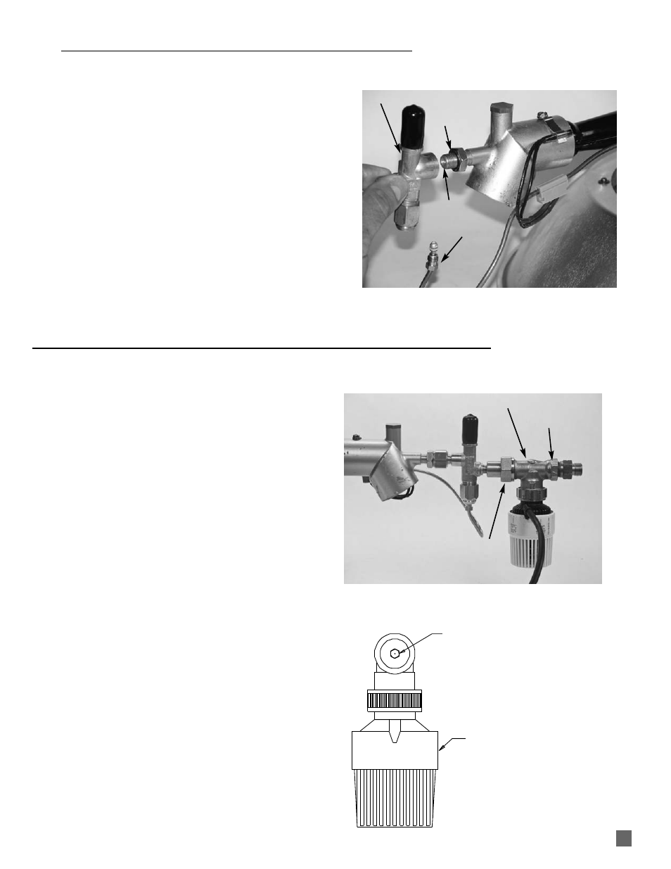
1. Disconnect the gas hose.
2. Disconnect the thermocouple from the safety valve.
3. Loosen the jam nut on the air housing.
4. Turning counterclockwise, remove the safety control.
When reassembling:
-- Ensure o-ring is seated in jam nut.
-- Apply Loctite (supplied with replacement) to first
four threads of air housing.
-- Thread the safety control valve onto the air
housing at least four full turns, and as needed to
allow the valve to be installed in an upright
position.
-- Thread the jam nut hand tight against the body of
the control and secure in place with a wrench.
FIG. 12
BYPASS ORIFICE
Individual Control Heaters
The bypass orifice is located in the modulating valve body of
individual controlled heaters. Its purpose is to supply low
pressure gas to the inner combustion cone when heat
demand is satisfied.
The orifice may become plugged with dirt after significant
heater use. A symptom of a plugged orifice is:
-- Inner cone goes out when thermostatic head cycles
heater back to low heat.
Refer to the following instructions:
1. Apply wrenches to the flats of the valve body and the
adapter nut. See Fig. 13.
2. Loosen the adapter nut at the outlet of the valve body.
3. Remove the thermostatic head with valve from the
heater. See Fig. 13.
4. Using a 3/16 in. nut driver, remove the orifice from
valve body. See Fig. 14. Replace if necessary. At
r e i n s t a l l a t i o n , f i r m l y s n u g i n to p l a c e . D o n ot
overtighten as thread damage may occur.
FIG. 13
FIG. 14
15
LOW FIRE ORIFICE
THERMOSTATIC
HEAD
BYPASS ORIFICE
THERMOSTATIC
HEAD
SAFETY GAS CONTROL VALVE
ADAPTER NUT
FLATS ON VALVE
MODULATING VALVE BODY
JAM NUT O-RING
THERMOCOUPLE
AIR
HOUSING
APPLY LOCTITE
SAFETY CONTROL VALVE