Installing dust filter, Fig. 6 – L.B. White I-17 Infraconic User Manual
Page 10
10
The zone control panel is a remote mounted control system
allowing the operation of a specific amount of heaters within
a certain zone of the building.
These panels will control the following quantity of heaters
depending on fuel type.
The zone control panel must be mounted to a flat, stable
wall inside the building. Use lag screws provided. For the
modulating zone panels, care must be taken to ensure that
the thermostatic control module is not exposed to outside
air temperatures. Exposure of the thermostatic control
module to outside air temperatures (Example: when
sidewall curtains are open) may cause the heater to provide
unwanted heat.
There are a number of optional configuration zone control
panels available. These include high and medium capacity,
modulating thermostatically controlled for stand alone, non-
electrical operation, as well as solenoid controlled for
incorporation into the building’s environmental control
system. Consult your local L. B. White dealer or distributor
or call the L. B. White Co. for recommendations on the best
configuration of zone panels for your specific application.
The zone control panel must have an adjustable high
pressure regulator installed upstream of the inlet of the
zone control panel. This regulator may be purchased from
the L. B. White Co. as an optional accessory. For L.P. gas,
the regulator must be capable of handling a maximum inlet
pressure of 10 psi, while supplying an outlet pressure of 5
psi nominal. This pressure is supplied to the zone control or
individual controlled heater. For natural gas, a regulator
must be installed to supply an outlet pressure of 5 psi
nominal.
ZONE CONTROL PANEL
COMPONENT FUNCTION AND INSTALLATION
Modulating System
Medium
High
Model and
Capacity
Capacity
Heat Output
Fuel
Panel
Panel
Quantity
Quantity
I17
L. P. Gas
14
(17,100 BTUH)
Natural Gas
8
40
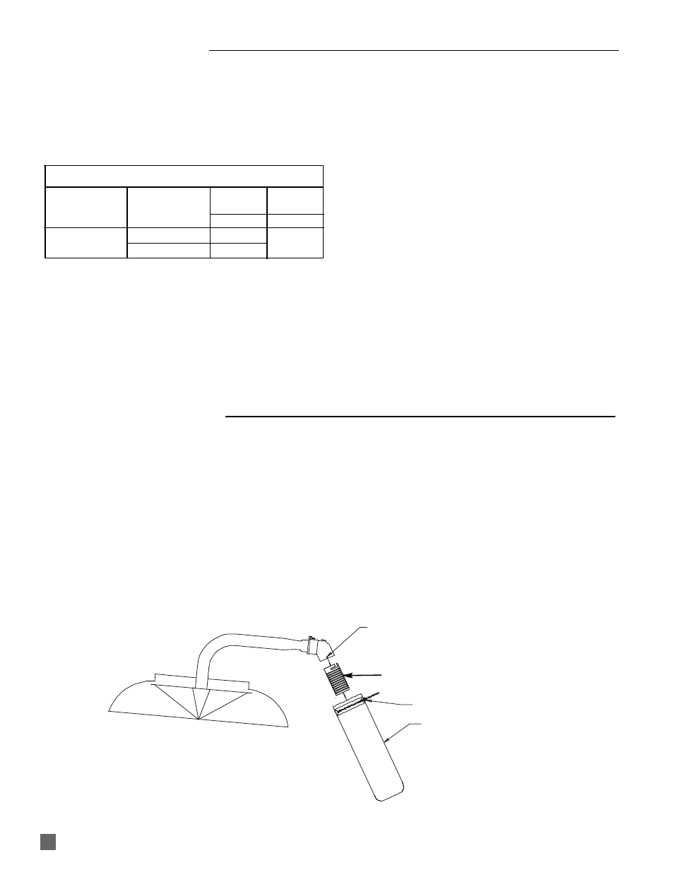
INSTALLING DUST FILTER
( Accessory)
FIG. 6
INJECTOR BODY TABS
FILTER ADAPTER
PART #23931
BEADED CABLE TIE
DUST FILTER
PART #23953
FILTER SLEEVE
FILTER
Although not required, the filter kit is recommended to
provide additional dust filtration capability and capacity for
Infraconic heaters when installed in severely dusty
environments.
1. Attach filter sleeve to air housing. The air housing
tabs fit into the slots on the sleeve. Rotate the sleeve
to lock it onto the air housing.
2. Position the filter onto the sleeve. Ensure all sleeve
holes are covered by the filter.
3. Securely attach the filter to the sleeve using the
beaded cable tie.
4. Ensure filter does not sag or touch heater’s canopy.
AIR HOUSING TABS