JVC DLA-HD2KU User Manual
Page 27
(No.PA019)1-27
4.4.5 16-PHASE VERTICAL BARS adjustment
PREPARATION
(1) Connect the Phase Deviation Measurement circuit at CN005 with the Projector turned off.Connect the FPC to a desired color.
(2) Connect the PC and Projector with a RS232C cable. Turn the projector ON and boot the SPA software.
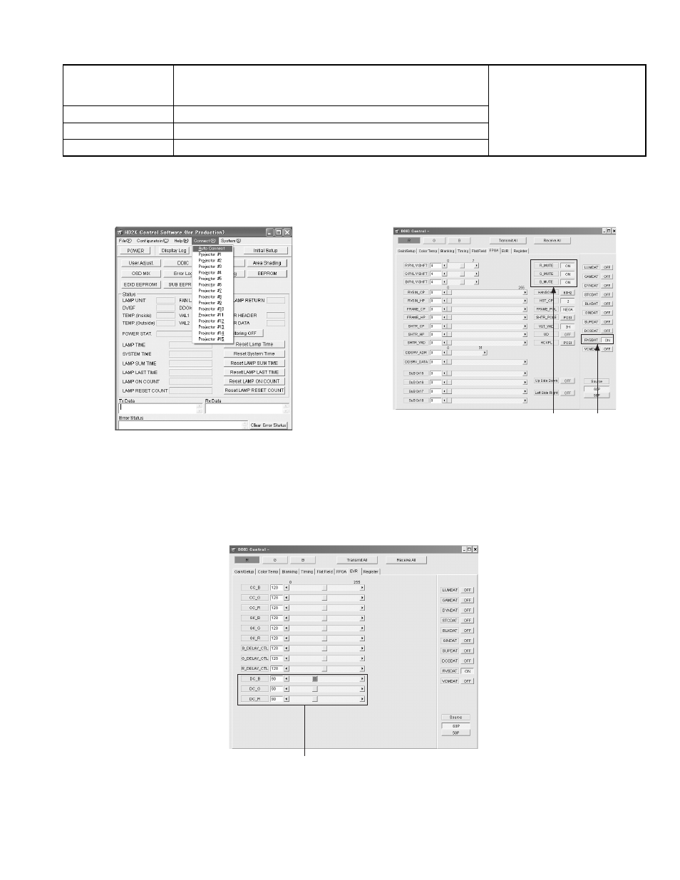
(3) Click [Connect] on the menu bar and select [Auto Connect] in the pull-down menu. Refer to Fig.1. (If [Connection failed] is
shown, the connection is FAILED. If no message appears, the connection is completed and the result is PASSED)
Fig.1
Fig.2
(4) When the connection is made, press [DDIC]. The DDIC Control screen will appear.
(5) Click [Receive All] at the top right of the screen.
(6) Press [R] at the top left of the screen.
(7) Of all buttons located at the furthest right of the screen, set [RVSDAT] to [ON] and the rest to [OFF]. Refer to Fig.2.
(8) Repeat the procedure in step (7) for the [G] and [B] buttons.
(9) Click the [EVR] tag in the DDIC Control screen.
(10) Set the values for [DC_R], [DC_G], [DC_B] to 90.
Refer to Fig.3.
Fig.3
(11) Press the [Load File] button in the [Register] tag in the DDIC Control screen.
(12) Select [PHS_RGBch_Inter-Phase Deviation_Clear.txt] and press [OK] in the [CONFIRM] message box.
(13) Set [R_MUTE], [G_MUTE], [B_MUTE] to ON in the [DDIC Control][FPGA] tag.
(14) Copy the entire contents of the [HD2K_16 Phase Adjustment_XX . Xls] file and modify the xxx to a serial number.
Instruments
PSA Software for HD2K
Phase deviation measurement circuit
Phase deviation measurement Excel file
REPLACING COMPONENTS
z
OPTICAL BLOCK
z
DD SUB1.2 PWB ASS'Y
Test point
Adjustment menu
< DDIC >
Preparation
Completed GAMMA adjustment
(10)ON
(7)ON
(10)Set these parameters to 90