Section 3 disassembly, 1 lens cover, 2 lamp unit cover – JVC DLA-HD2KU User Manual
Page 13: 3 top cover, 4 protect cover, 5 control unit
(No.PA019)1-13
SECTION 3
DISASSEMBLY
Notes:
• Confirm that the power cord is unplugged from the AC outlet before proceeding.
• The lamp remains quite hot after turning the power off. Allow sufficient time to cool before starting work.
3.1
LENS COVER
(1) Rotate the LENS COVER on the front of the main frame
counterclockwise and release the lock. Then pull out the
LENS COVER toward you. (Fig.1)
3.2
LAMP UNIT COVER
(1) Loosen the 2 screws marked A on the right side of the main
frame and pull out the LAMP UNIT COVER toward you.
(Fig.2)
These 2 screws are not removed from the LAMP UNIT
COVER.
3.3
TOP COVER
• Remove the LENS COVER.
• Remove the LAMP UNIT COVER.
(1) Remove the 1 screw marked B and the 2 screws marked C
on the right side of the main frame. (Fig.2)
(2) Remove the 3 screws marked D on the left side of the main
frame. (Fig.2)
(3) Remove the 1 screw marked E on the rear side of the main
frame. (Fig.2)
(4) Remove the harness from the connector
CN701
of the
CONTROL UNIT which is secured to the back of the TOP
COVER.
(5) Lift up the TOP COVER to remove it.
3.4
PROTECT COVER
• Remove the LENS COVER.
• Remove the LAMP UNIT COVER.
• Remove the TOP COVER.
(1) Remove the 1 screw marked E' fixing the PROTECT COV-
ER, and lift up the PROTECT COVER to remove it. (Fig.2)
3.5
CONTROL UNIT
• Remove the LENS COVER.
• Remove the LAMP UNIT COVER.
• Remove the TOP COVER.
(1) Remove the 5 screws marked F fixing the CONTROL UNIT
from the back of the TOP COVER. (Fig.2)
(2) Remove the CONTROL UNIT. (Fig.2)
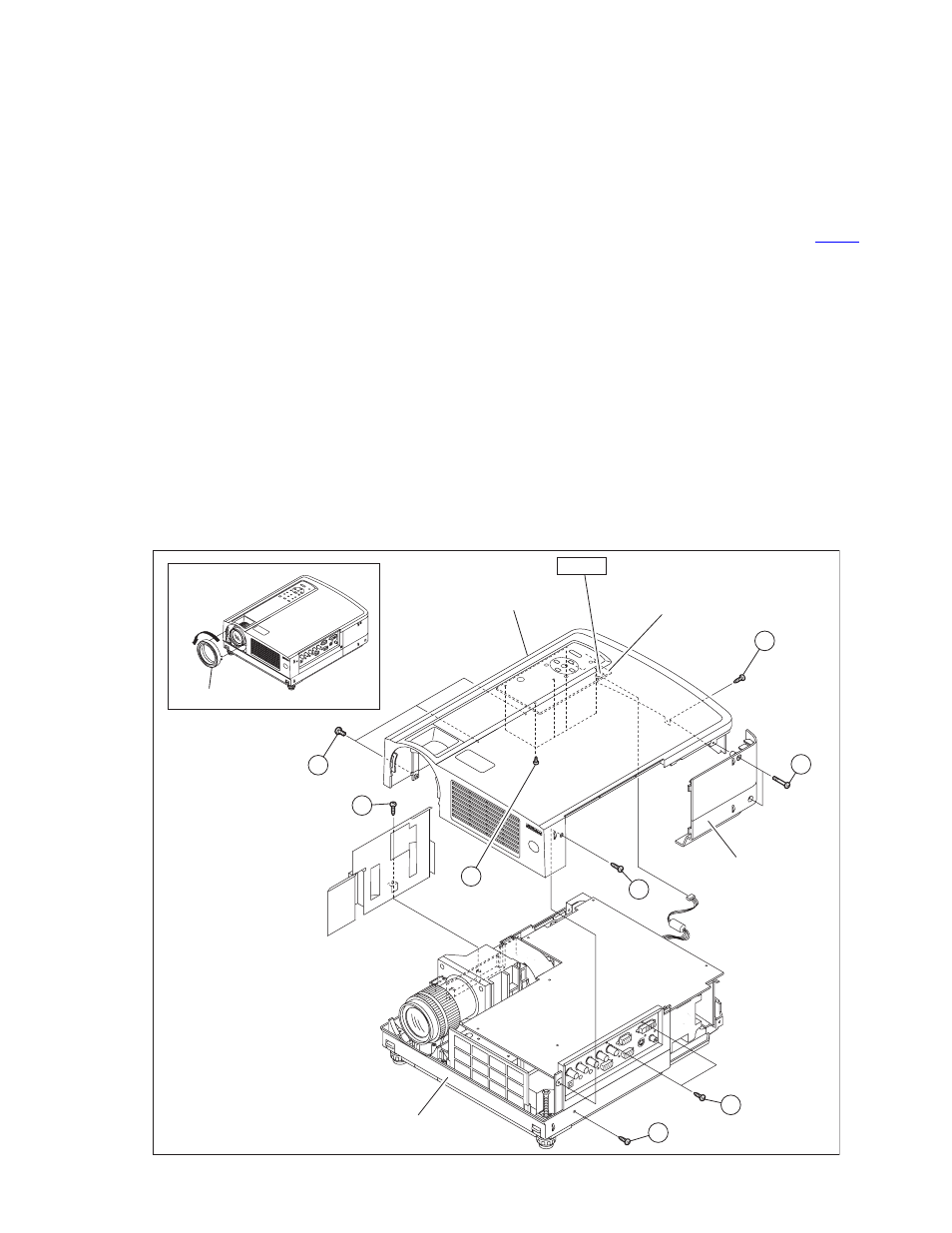
Fig.2
TOP COVER
BOTTOM CHASSIS
CONTROL UNIT
LAMP UNIT COVER
E
A
(x2)
(x1)
(x1)
(x1)
(x1)
D
(x3)
E'
C
B
(x2)
C
(x5)
F
CN710
LENS COVER
Fig. 1