Fitting procedure bull bar preparation – ARB 3915030 User Manual
Page 13
Last Rev Date: 29/10/2008
Page 13 of 24
Fitting instructions# 3783321
Copyright © 2005 by ARB Corporation Limited. All rights reserved, this document must not be reproduced without the express authority of ARB Corporation Ltd
FITTING PROCEDURE BULL BAR PREPARATION
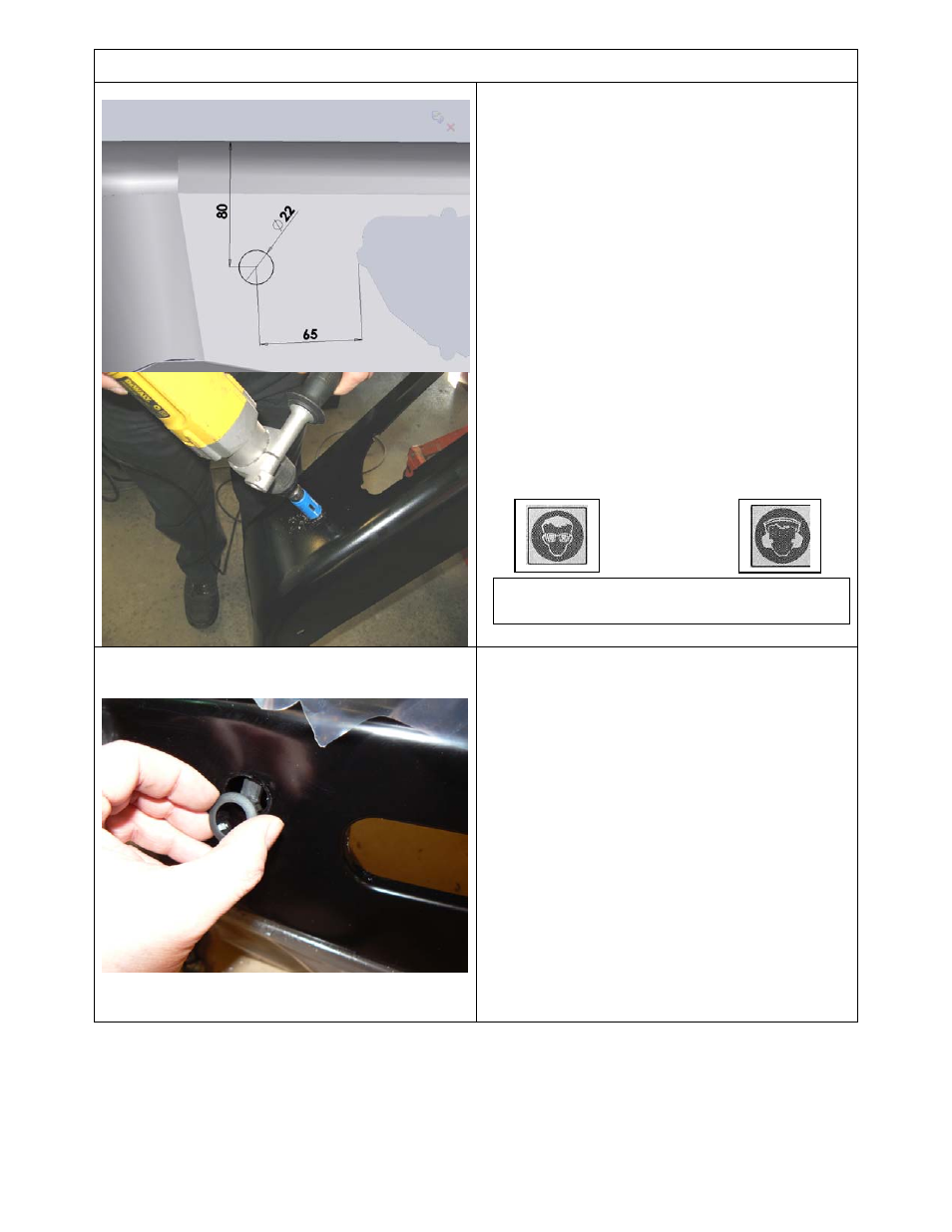
40.
If sensors are to be refitted, position the
bar face up and mark out the hole position
as shown on both wings. Dimensioned
80mm from the top of the wing and 65mm
from the most outboard edge of the light
aperture. This position is optimal for
sensor operation.
41.
Carefully drill the hole with Dia 22.0mm
(7/8”) hole saw.
CAUTION: Do not make the hole smaller
than shown, Dia 22.0 – 22.3 is ideal.
42.
Deburr any sharp edges.
43.
Test fit the sensor sleeve checking that it
fits and is not too tight, the inner bore of
the sleeve must not be reduced in
diameter.
44.
Once sensor hole is cut and sensor has
been trial fitted, paint the raw metal edges
to prevent corrosion.
45.
Fit sensor sleeve into bar first as
shown, noting that the tab at rear is up
for RHS of bull bar and down for LHS
(the same orientation as original OE).
Then fit sensor into sleeve.
46.
Fit loom extensions and push anchor
plug into slot in wing brace
Note: Connections are always inboard.
Hint: Take care not to damage sensor
electrical connections when removing and
refitting.
Warning: Drilling operations can result in
flying metal debris, safety glasses should be