IDEX Health & Science REGLO CPF Digital Version with Settings Menu User Manual
Page 48
REGLO-CPF Digital/ISMATEC SA/8.12.06/CB/GP/TM
48
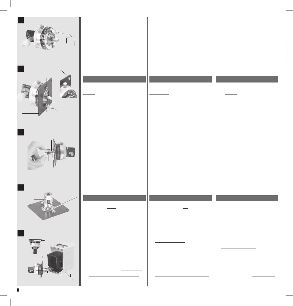
1 Attaching the mounting
plate
Remove screws (b) and serra-
ted lock washers (c) from the
pump-head.
2 Fasten the mounting-plate (3)
on the pumphead with the 2
screws (b) and serrated lock
washers (c).
IMPORTANT
The 4 countersinks (5) must be
concave to the pump-head.
3 Fixing the coupling
Place the completely assem-
bled coupling (2) onto the
pumphead shaft and push it
on as far as it will go. The Al-
lan screw (d) must be pointing
towards the flat part of the
pumphead shaft (e).
4 Tighten the coupling (2) with
the Allan key size 2.5 mm (5).
5 Mounting the pump-head
Important
– The scale of the red flow control
ring (f) must be pointing up-
wards
– Hold the mounting plate in such
a way, that the screws (b) are on
the top and at the bottom
– Turn the coupling, so that after-
wards the Allan screw (d) can be
tightened through the aperture
(g) with the Allan key (5)
– Insert the pumphead assembly
and push it on as far as it will go.
Check the position of the Allan
screw at the aperture (g)
1 Installation de plaque de
montage
Dévisser les vis (b) et les enlever
de la tête de pompe avec les
rondelles (c).
2 Fixer la plaque de montage (3)
sur la tête de pompe avec les 2
vis (b) et les rondelles (c).
IMPORTANT
Les 4 noyures (5) doivent être diri-
gées contre la tête de pompe.
3 Installation de la pièce
d‘accouplement
Placer la pièce d'accouplement
assemblée (2) sur l'arbre de la
tête de pompe et la pousser
jusqu'à la butée. La vis à six
pans (d) doit être dirigée con-
tre la partie plate de l'arbre de
la tête de pompe (e).
4 Fixez la pièce d'accouplement
(2) au moyen de la clé pour vis
à six pans de la taille 2.5 mm (5).
5 Installation de la tête de pompe
Important
– La graduation de l’anneau gra-
dué rouge (f) doit être dirigée
vers le haut.
– Maintenir la plaque métallique
de telle façon que les vis (b) se
situent au-dessus et au-des-
sous.
– Tourner le coupleur de telle
façon que la vis à six pans
(d) puisse être fixée à travers
l’ouverture (g).
– Introduire l’unité de tête
jusqu’à la butée. Contrôler la
position de la vis à six pans (g)
1 Montageplatte montieren
Schrauben (b) und Fächer-
scheiben (c) vom Pumpenkopf
entfernen.
2 Montageplatte (3) mit den 2
Schrauben (b) und Fächerschei-
ben (c) am Pumpenkopf befes-
tigen.
WICHTIG
Die 4 Versenkungen (5) müssen
gegen den Pumpenkopf gerichtet
sein.
3 Kupplungsstück montieren
Das zusammengebaute Kupp-
lungsstück (2) auf Pumpen-
kopfwelle aufsetzen und bis
zum Anschlag schieben. Die In-
nensechskantschraube (d) muß
gegen die flache Hälfte der
Kopfwelle (e) gerichtet sein.
4 Befestigen Sie das Kupplungs-
stück (2) mit dem Innensechs-
kantschlüssel 2.5 mm (5).
5 Pumpenkopf montieren
Wichtig
– Skala des roten Skalenrings (f)
nach oben drehen
– Montageplatte so halten, dass
Schrauben (b) oben und unten
sind
– Kupplung so drehen, dass die
Innen-Sechkantschraube (d)
mit dem Sechskantschlüssel (5)
durch die Öffnung (g) fixiert
werden kann
– Die Kopf-Einheit bis zum An-
schlag einführen. Innensechs-
kant-Schraubenposition (g)
kontrollieren.
4
5
2
5
f
b
b
d
g
5
2
5
5
5
5
b+c
b+c
3
d
2
e
1
c
b
5