Nstalling, Component side down, Smart plug s-video video audio rf in – Philips SCN727C199 User Manual
Page 5: Mart
9
SMART
PLUG
S-VIDEO
VIDEO
AUDIO
RF IN
1
VIDEO
AUDIO
IN
OUT
OUT
IN
S-VIDEO
S-AUDIO
S-AUDIO
VGA IN
VGA OUT
RS 232
3
2
Component
Side Down
CLONE
PORT
S-VIDEO
VIDEO
AUDIO
RF IN
VIDEO
AUDIO
IN
OUT
OUT
IN
S-VIDEO
VGA/S-AUDIO
S-AUDIO
VGA IN
VGA OUT
RS 232
PHILIPS
ScanCard II
E
NH
A
N C
E
D
FOC
US
ScanCard II and
Cover Assembly
Guide Pins
32 Pin Connector
Rear of SmartCard II Television
RF IN (Antenna Jack)
Hex Head Screws
Push Here
When Installing
CLONE
PORT
S-VIDEO
VIDEO
AUDIO
RF IN
VIDEO
AUDIO
IN
OUT
OUT
IN
S-VIDEO
VGA/S-AUDIO
S-AUDIO
RS 232
VGA IN
VGA OUT
E
N H
A NCE
D
FOCUS
ScanCard II
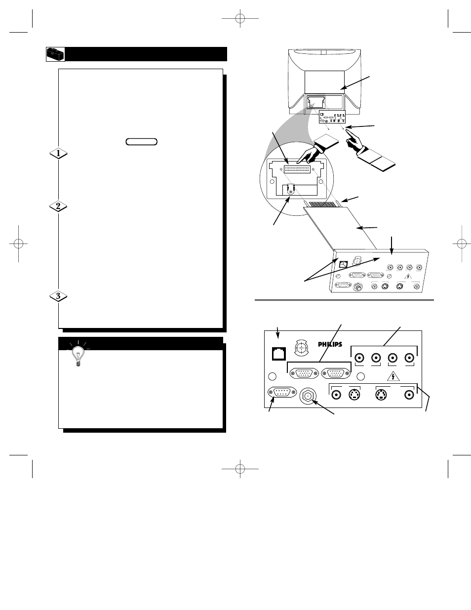
Clone Port - 6 Pin
Connector for limited
applications.
VGA Inputs and Outputs
(Loop Thru)
AUDIO/VIDEO Inputs
and Outputs
(Loop Thru)
VGA/S-VIDEO/S-AUDIO Inputs
and Outputs (Loop Thru) (S-AUDIO
In/Outputs are Audio jacks used
only with the S-VIDEO In/Outputs)
RF IN -
Antenna/Cable
75
Ω
Input
RS 232 SmartLink™ Connector
for interface between the TV and
a computer (PC or MAC).
I
NSTALLING
S
CAN
C
ARD
II
8
I
nstallation of the ScanCard II is easy.
Remember to follow these instructions, be
patient, and use the T374AH Set Up Remote
Control (see T374AH Remote Control
Instructions - part # IB7166E002 for complete
details). Note: This is not the remote supplied
with the ScanCard II package.
Start by unplugging the AC power cord
from the wall socket. Remove the hex head
screws holding the card cover in place. Slide the
card cover off. Be careful when pulling the
Antenna jack (RF IN) out of its plug.
Insert the ScanCard II (with its components
facing down) into the back of the TV. Line up
and guide the 32 pin connector into place. Note:
There are guide pins to help line up the Card
properly. Gently, but firmly, press the card into
place by pushing on the card cover directly in line
with the circuit board itself.
DO NOT press the card into place by pushing on
the corners of the card cover.
Press the RF IN (Antenna) jack firmly into
its plug and replace the hex head screws to secure
the card and card cover to the rear of the TV.
BEGIN
Remember, unplug the TV to avoid electrical
shock damage to the TV.
Be sure to align the 32 pin connector before pressing into
place. Never force the ScanCard II into the connector. If it
will not go in smoothly, realign the guide pins and try
again.
Do not use the ScanCard II jacks to push the card
assembly into place. Push on the cover directly behind
the card itself.
S
MART
H
ELP
SCAN 2 10/3/00 10:49 AM Page 8