Philips BDH5011-74 User Manual
Page 16
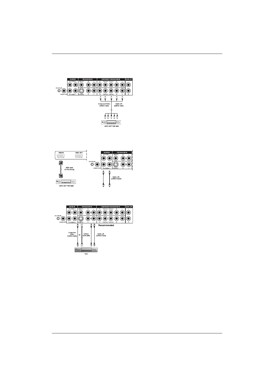
7.2 Connecting a HDTV
Decoder Set-Top Box
Using Component Video Input
1. Connect the green (labeled as Y) jack from
the HDTV Set-top box to the green Y1 jack
of the display.
2. Connect the red (labeled as PR or CR) jack
from the HDTV Set-top box to the red
PR1/CR1 jack of the display.
3. Connect the blue (labeled as PB or CB)
jack from the HDTV Set-top box to the blue
PB1/CB jack of the display.
4. Connect the red (R) and white (L) audio
jacks from the HDTV Set-top box to the R
and L audio-in jacks located next to the
PR1/CR connector.
Using RGB Input
1. Connect the 15-pin D-Sub RGB connector
from the back of the HDTV Set-top box to
the RGB-IN connector located on the back
of the display.
2. Connect the red (R) and white (L) audio-out
jacks from the HDTV Set-top box to the R
and L audio-in jacks located to the left of the
S-VIDEO connector.
7.3 Connecting
a
VCR
Using S-Video Input
1. Connect the S-Video (4-pin DIN) connector
from the VCR to the S-VIDEO input on the
back of display.
2. Connect the red (R) and white (L) audio
jacks from the VCR to the R and L audio-in
jacks located next to the S-VIDEO
connector.
Using Composite Input
1. Connect the yellow (video) out connector
from the VCR to the yellow Video 1 input on
the back of the display.
2. Connect the red (R) and white (L) audio-out
jacks from the VCR to the R and L audio-in
jacks located next to the yellow Video
connector.
16
User Manual BDH5011