Controls, indicators and connector specifications – B&B Electronics Vlinx MESR9xx User Manual
Page 48
9. Appendices
Vlinx MESR9xx Modbus Gateway
Page 44
Manual Documentation Number MESR9xx-4508m
www.bb-elec.com/
www.bb-europe.com/
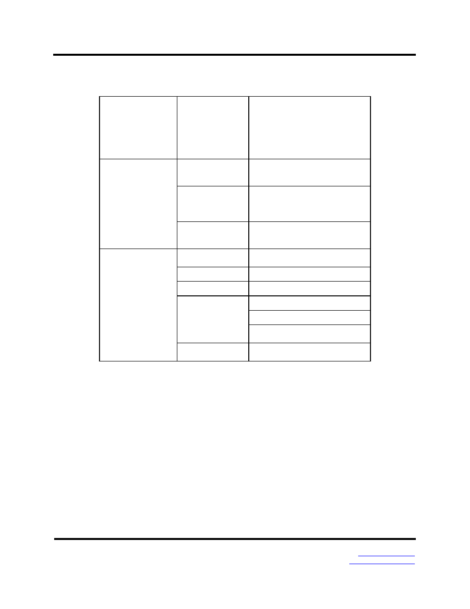
Controls, Indicators and Connector Specifications
Switches
Reset button
Hold in for 0 to 2 seconds for hardware
reset
Hold in for 2 to 10 seconds for Console
Mode (Do a hardware reset or recycle
power to exit Console Mode)
Hold in for more than 10 seconds to
reset to factory defaults
Indicators
Serial LED
(one per port)
Color = Green
On = Port open
Blink = Data traffic
Link LED
Color = Green
On = 100BaseTX
Off = 10BaseT
Blink = Data traffic
Ready LED
Color = Green
Blink (once per second) = System OK
Off = System NOT OK
Connectors
10BaseT/100BaseTX
Ethernet
Single RJ-45F (8 pin)
SC fiber
SC connector
ST fiber
ST connector
Serial
ESR901-x: one DB-9M connector
ESR902D-x: Two DB-9M connectors
ESR902T-x: Two pluggable lockable
5.08 mm terminal blocks
DC Power
5.08mm 2-position pluggable, lockable
terminal block