Table 36 — start-up mode sequence, Table 38 — input/output channels – Bryant DuraPac Series 580f User Manual
Page 41
—
41
—
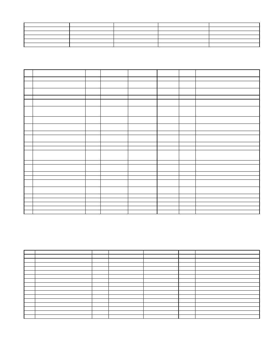
Table 36 — Start-Up Mode Sequence
LED — Light-Emitting Diode
Table 37 — Configuration Variables (Read and Setup Modes)
LEGEND
NOTE: The accessibility of these channels will be as follows:
READ MODE — All channels will be accessible.
SETUP MODE — Only channels 1-20 will be accessible and 20 will be used to
reset alarms.
Table 38 — Input/Output Channels
NOTE: The accessibility of these channels will be as follows:
READ MODE — All channels will be accessible for reading.
ADJUST MODE — Only channels 1-5 will be accessible.
MANUAL MODE — Only channels 1-5 will be accessible.
TIME
LED 1/DS1 (RED)
LED 2/DS2 (YELLOW)
LED 3/DS3 (GREEN)
LED 4/DS4 (GREEN)
0-1.0 SEC
OFF
OFF
OFF
OFF
1-1.5 SEC
FLASH ½ SEC
OFF
OFF
OFF
1.5-2.0 SEC
OFF
FLASH ½ SEC
OFF
OFF
2.0-2.5 SEC
OFF
OFF
FLASH ½ SEC
OFF
2.5-3.0 SEC
OFF
OFF
OFF
FLASH ½ SEC
NO.
SETUP POINTS
(viewable and adjustable)
UNITS
MINIMUM
VALUE
MAXIMUM
VALUE
FACTORY
SETTING
INC
COMMENTS
1
Supply Air Temperature Setpoint
F
40 F
65 F
55 F
1 F
Leaving Air Temperature Control Point
2
Occupied Minimum Economizer
Position
%
Item 15 +1%
100%
15%
1%
Min Econo Position (occupied mode)
3
Unoccupied Minimum Economizer
Position
%
1%
100%
5%
1%
Min Econo Position (unoccupied mode)
4
Economizer Maximum Position
%
1%
100%
100%
1%
Maximum Econo Position
5
Economizer Type
—
1
3
2
1
1 = Vent Only, 2 = Proportional,
3 = 3 Position
6
Economizer Changeover Type
—
1
5
2
1
1 = Switch, 2 = Outdoor Dry Bulb,
3 = Diff Dry Bulb, 4 = Outdoor Enthalpy,
5 = Diff Enthalpy
7
Economizer Changeover Setpoint
(mode 2)
F
45 F
70 F
65 F
1 F
For Outdoor Changeover
8
Economizer Changeover Setpoint
(mode 3)
—
1
4
1
1
Outdoor Enthalpy Changeover Setpoint
1 = A, 2 = B, 3 = C, 4 = D
9
No. of compressors
—
1
4
2
1
1, 2, 3, or 4
10
Compressor Sequencing
—
1
4
1
1
1 = DC-Sensible, 2 = DC-Latent,
3 = LAT-Sensible, 4 = LAT-Latent
11
Power Exhaust Stage 1 Activation
%
1%
Item 12 -5%
25%
1%
Economizer Position
12
Power Exhaust Stage 2 Activation
%
Item 11 +1%
100%
50%
1%
Economizer Position (> stage 1)
13
Unoccupied Configuration
—
1
3
3
1
1 = No Unoccupied Cooling,
2 = Unoccupied Free Cooling,
3 = Unoccupied Free & Mech Cooling
14
Compressor Lockout Temperature
—
1 F
65 F
45 F
1 F
Compressor Operation
15
IAQ Min Economizer Position
Setpoint
%
1%
Item 2 +1%
5%
1%
Min IAQ Position for VOC Emissions
16
IAQ Enable
—
1
2
1
1
1 = Disabled, 2 = Enabled
17
Outdoor IAQ Reference
PPM/10
1 PPM/10
100 PPM/10
40 PPM/10
1 PPM/10 Outdoor Reference IAQ Level
18
IAQ Lower Limit Control Point
Differential
PPM/10
1 PPM/10
Item 19 -1
PPM/10
60 PPM/10
1 PPM/10
Differential Lower Limit Indoor
IAQ Level
19
IAQ Upper Limit Control Point
Differential
PPM/10
Item 18 +1
PPM/10
200 PPM/10
140 PPM/10
1 PPM/10
Differential Upper Limit Indoor
IAQ Level
20
1st Most Recent Error/Reset
—
1
8
—
—
Used in Setup Mode to Reset Alarms
21
2nd Most Recent Error (read only)
—
1
8
—
—
Not Displayed in Setup Mode
22
3rd Most Recent Error (read only)
—
1
8
—
—
Not Displayed in Setup Mode
23
4th Most Recent Error (read only)
—
1
8
—
—
Not Displayed in Setup Mode
24
5th Most Recent Error (read only)
—
1
8
—
—
Not Displayed in Setup Mode
DC
— Direct Control
IAQ
— Indoor Air Quality
LAT — Leaving Air Temperature Compensated Control
VOC — Volatile Organic Compounds
NO.
I/O POINTS
UNITS
MINIMUM VALUE
MAXIMUM VALUE
INC
COMMENTS
1
C1 Output
—
Off
On
—
Compressor 1
2
C2 Output
—
Off
On
—
Compressor 2
3
C3 Output
—
Off
On
—
Compressor 3/Power Exhaust 2
4
C4 Output
—
Off
On
—
Compressor 4/Power Exhaust 1
5
Economizer Damper Output
%
1 F
100 F
1%
Damper Commanded Position
6
Supply Air Temperature
F
1 F
150 F
1 F
Supply Air Temperature
7
Outdoor Air Temperature
F
1 F
150 F
1 F
Outdoor Air Temperature
8
Return Air Temperature
F
1 F
150 F
1 F
Return Air Temperature
9
Indoor Relative Humidity
%
1%
100%
1%
Return Air Relative Humidity
10
Outdoor Relative Humidity
%
1%
100%
1%
Outdoor Air Relative Humidity
11
Indoor Air Quality
PPM
1 PPM/10
200 PPM/10
10 PPM
Indoor Air Quality (/10)
12
Remote Minimum Position
%
1%
100%
1%
Remote Minimum Pot Position
13
Y1 Status
—
Open
Close
—
Thermostat Y1 Status
14
Y2 Status
—
Open
Close
—
Thermostat Y2 Status
15
G Status
—
Open
Close
—
Indoor Fan Status
16
Occ Status
—
Open
Close
—
Remote Occupied Status