Table 35 — economi$er+ inputs and outputs, Fig. 36 — economi$er+ controller board – Bryant DuraPac Series 580f User Manual
Page 40
—
40
—
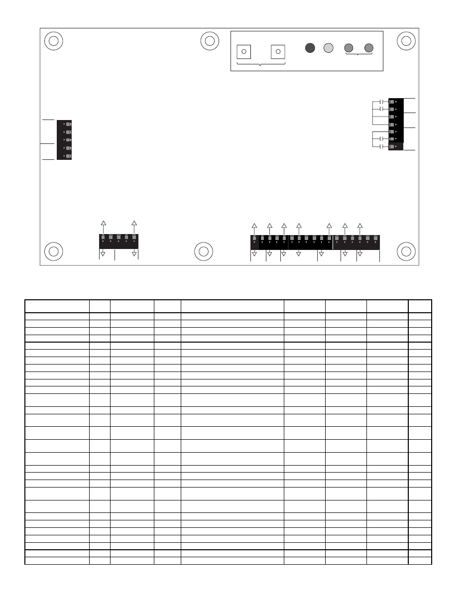
Table 35 — EconoMi$er+ Inputs and Outputs
*If there are 3 stages then there can only be 1 stage of power exhaust.
†If there are 4 stages then no power exhaust stages are directly controlled.
INPUT
NAME
TYPE
USE
INPUT/OUTPUT
RANGE
CONVERSION
RANGE
CONVERSION
RESOLUTION
CONNECTION
PIN
NO.
THERMOSTAT INPUTS
Y1 (Cool/Low Cool)
Y1
Switch
Standard
18-30 vac 50/60 Hz w/min 24 mA Load
NA
On/Off
J1
1
Y2 (Cool 2/High Cool)
Y2
Switch
Option
18-30 vac 50/60 Hz w/min 24 mA Load
NA
On/Off
J1
2
G (fan)
G
Switch
Standard
18-30 vac 50/60 Hz w/min 24 mA Load
NA
On/Off
J1
3
Occupied/Unoccupied
OCC
Switch
Option
18-30 vac 50/60 Hz w/min 24 mA Load
NA
On/Off
J1
4,5
POWER
Power
24V
Input
Standard
18-30 VAC 50/60 Hz
NA
NA
J2
1,2
ECONOMIZER MOTOR
Control
CNT
2-10 vdc
Standard
2-10 vdc
0-100%
1%
J2
3,4,5
ANALOG INPUTS
Supply Air Temperature
SAT
10 K Thermistor
Standard
1816 to 86407 Ohms
30 to 125 F
0.8 F
J3
1,2
Outside Air
Temperature
OAT
10 K Thermistor
Standard
1816 to 86407 Ohms
30 to 125 F
0.8 F
J3
3,4
Return Air Temperature
RAT
10 K Thermistor
Option
1816 to 86407 Ohms
30 to 125 F
0.8 F
J3
5,6
Indoor Humidity
IRH
4-20 mA,
Loop Powered
Option
4-20 mA, 24 vdc
0-100%
.08 mA
J3
7,8,9
Outdoor Humidity
ORH
4-20 mA,
Loop Powered
Option
4-20 mA, 24 vdc
0-100%
.08 mA
J3
10,11,1
2
Indoor CO
2
IAQ
4-20 mA,
Ext Sourced
Option
4-20 mA, 24 vdc
0-200 PPM/10
10 PPM
J3
13,14
Remote Minimum
Position Pot
MIN
10K
Option
10K to 100K Ohms
0 to 100%
1%
J3
15,16,1
7
RELAY OUTPUTS
Cooling Stage 1
CP1
Relay
Standard
24 vac, 2.5 Amps at 24 vac
NA
On/Off
J4
1,3,4
Cooling Stage 2
CP2
Relay
Option
24 vac, 2.5 Amps at 24 vac
NA
On/Off
J4
2,3,4
Power Exhaust 2/
Cooling Stage 3*
CP3/
EX2
Relay
Option
24 vac, 2.5 Amps at 24 vac
NA
On/Off
J4
5,6
Power Exhaust 1/
Cooling Stage 4†
CP4/
EX1
Relay
Option
24 vac, 2.5 Amps at 24 vac
NA
On/Off
J4
5,7
DISPLAY
Setpoint Switch 1
SP1
Digital
Standard
Open/Closed
Logic
Open/Closed
On Board
NA
Setpoint Switch 2
SP2
Digital
Standard
Open/Closed
Logic
Open/Closed
On Board
NA
LED 1
DS1
LED Output
Standard
Red
Logic
On/Off
On Board
NA
LED 2
DS2
LED Output
Standard
Yellow
Logic
On/Off
On Board
NA
LED 3
DS3
LED Output
Standard
Green
Logic
On/Off
On Board
NA
LED 4
DS4
LED Output
Standard
Green
Logic
On/Off
On Board
NA
Y1
Y2
G
OCC
24V
1
J1
5
Y1 (cool 1)
Y2 (cool 2)
G (fan)
OCC
24 VAC
THERMOST
A
T
INPUTS
Occupied/unoccupied
I/O support dry circuit
contact (min 24 mA I)
POWER
SUPPLY
2-10 VDC
ECONOMIZER
CONTROL
J2
1
5
CNT
24V
24V
24
V
A
C
24
V
A
C
Control
SA
T
OA
T
RA
T
IRH
VRF
ORH
VRF
IAQ
MIN
VRF
IAQ
(4-20ma)
min
(10K
pot)
ORH
(4-20
ma)
V
ref
V
ref
V
ref
IRH
(4-20
ma)
RA
T
(10k
thermistor)
OA
T
(10k
thermistor)
SA
T
(10k
thermistor)
J3
1
17
ANALOG INPUTS
4-20 mA external powered between signal and ground
4-20 mA loop powered between 24 VDC and signal
Relays rated at 24 VAC 3A
and traces for 8A.
NOTE: For 1 and 2 stage
cooling, 2 stages of power
exhaust will be used.
For 3 cooling stages, only 1
stage of power exhaust will be
used, and for 4 stages no power
exhaust will be controlled
directly by the control.
OUTPUT
RELA
YS
C1
C2
24V
24V
24V
C3
C4
24 VAC
24 VAC
24 VAC
CP1
CP2
EX2/CP3
EX1/CP4
J4
READ/
ADJUST
ADVANCE
MANUAL
DS1
DS2
SETPOINT DISPLAY
DS3
DS4
date or serial no
RED YELLOW
GREEN
PUSH BUTTONS
# 1
# 2
Fig. 36 — EconoMi$er+ Controller Board