Briggs & Stratton 202826GS User Manual
Page 13
13
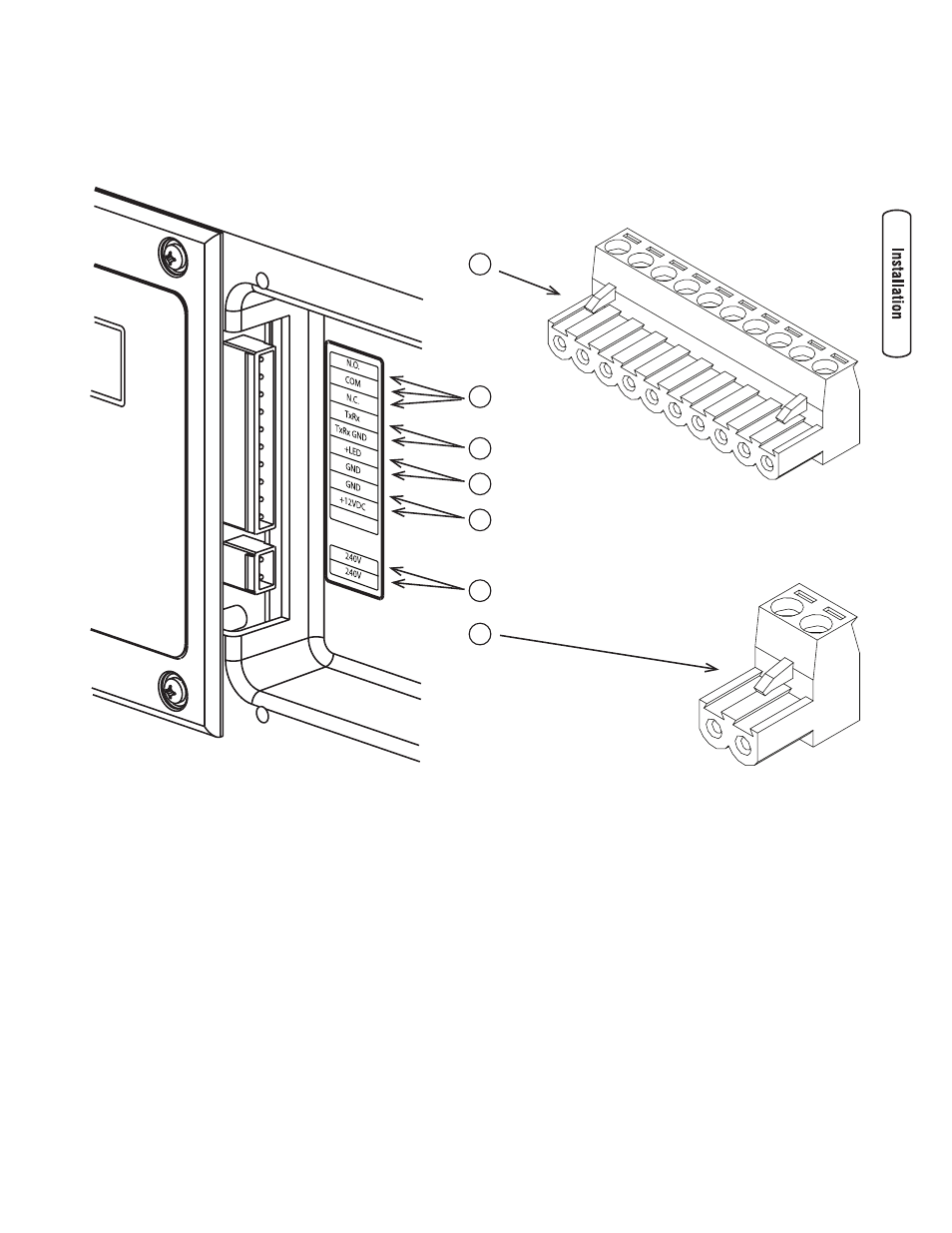
System Connectors
Exceptforthepoweroutputandgroundingconnectors,allsignalwireconnectionsaremadetoremovabletwo-orten-pin
connectorplugs.Comparethisillustrationwithyourgeneratortofamiliarizeyourselfwiththelocationoftheseimportant
connections:
A - 10 Pole Connector Plug
B - Fault Contacts—UseNO,COMandNCtohookupa
siren,light,optionalGenAlert,etc.toalertyouincase
ofafault.Contactsreversestate(NOgoestoNCand
viceversa)uponafaultcondition.
C - Transfer Switch Communication—UseTxRxandTxRx
GNDtotransferswitchtomonitorgeneratorfunctions.
D - Remote LED Output—Usethistohookuptheremote
LEDsuppliedwiththegenerator.TheremoteLEDwill
turnonandoffinaseriesofblinksifcertainfaultsare
detectedinthegenerator.
E - +12 Volt DC, .5 Amp Output —Internalpowersupply.
F - 240 Volt Utility—Usetohookupthe40Vutilityleads
fromthetransferswitchtothegenerator.
G - 2 Pole Connector Plug
B
A
C
D
E
F
G