Liebherr LTM 1200-5.1 User Manual
Page 8
PN 1200-5.1_D-GB/F/I/ESP/RUS 04.07.2007 11:23 Uhr Seite 7
Probedruck
C
M
Y
CM
MY
CY CMY
K
9
8
LTM 1200-5.1
LTM 1200-5.1
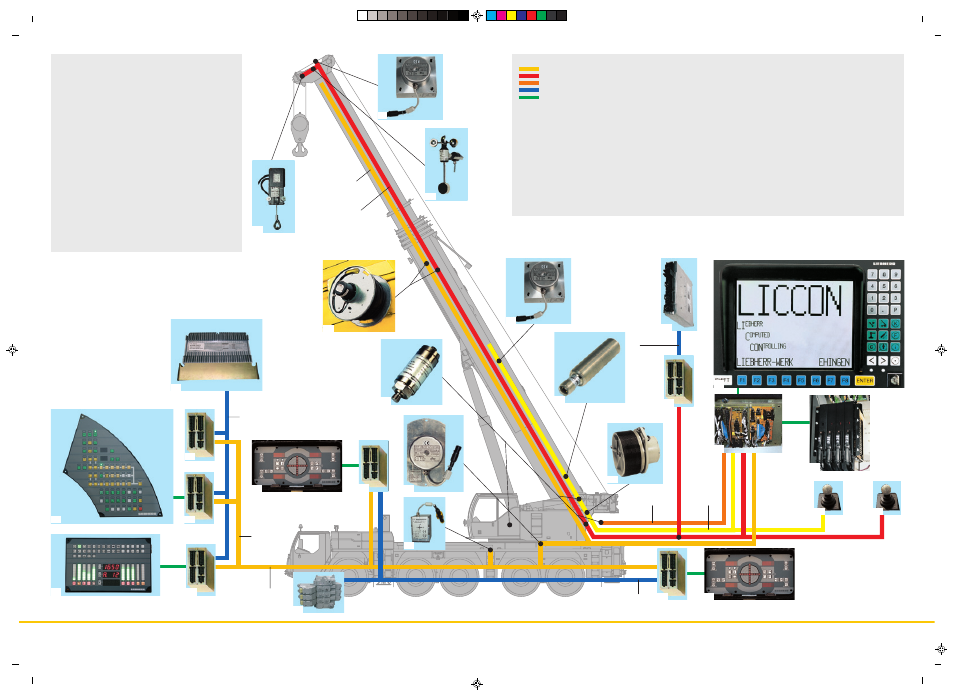
• The electric and electronic components are interconnected
by the latest data bus transmission technique
• Instead of the traditional electric wiring, the data transmission
to the individual function blocks is performed digitally just
by a few data cables, thus improved reliability due to
essentially less contacts
• Self-manufactured Liebherr bus systems (LSB), specially
adapted to the requirements of a mobile crane
• Diesel engine and automatic transmission are controlled by
a CAN data bus. The all electronic drive management reduces
fuel consumption and improves the exhaust gas emission
• The electric systems of the carrier and crane as well as of
all cockpit functions, the outrigger system and sensor system
of the boom are interconnected by 4 Liebherr system busses
• The control of the function blocks is realized by I/A modules
the programming of which is performed by means of the
Liebherr system busses. The control intelligence is integrated
into the LICCON central unit
• Comprehensive diagnostic facilities, quick error localization,
operating error display
• Test programs for functional test of keyboard and display
unit as well as for the test of the control units for engine
and transmission management, additional Liebherr brake
system, hydraulic ventilator, hydraulic suspension and
outrigger control panels
• The new data bus technique distinctively increases
functionality and efficiency of the mobile crane
LSB -
LSB -
LSB -
CAN -
SCI -
Legend:
LSB - Liebherr system bus 1
LSB - Liebherr system bus 2
LSB - Liebherr system bus 3
CAN - Busses
SCI - Serial Communication Interface
1 Input/output module for control of the suspension, Liebherr
Diesel engine, automatic transmission, control functions,
pneumatic control of brake functions
1a Instruments keyboard unit in driver’s cab
2 Input/output module for differential locks, display functions
2a Instruments keyboard unit in driver’s cab
3 Input/output module for outrigger system - right
3a Control unit for outrigger system - right
4 Input/output module for outrigger system - left
4a Control unit for outriggers system - left
5 Input/output module for engine brake, cruise controller, speed
setter, electronic control of Diesel engine (steering column
switch right) and automatic transmission
6 Control of Liebherr Diesel engine/carrier and automatic
transmission
7 Inclination sensor for automatic levelling
8 Slewing sensor in slipring unit
9 Connection of Liebherr system bus (LSB 1, 2, 3, 4)
10 LICCON central unit
11 LICCON monitor in crane cab
12 Length sensor and cable drum/energy cable for interlocking
gripper/telescopic boom
13 Inductive sensors (12 x)
14 Angle sensor on base section
15 Cable drum for items 16, 17, 18 and for luffing jib
16 Wind sensor
17 Hoist limit switch
18 Angle sensor
19 Input/output module for electronic control of Diesel
engine/superstructure, air flap, ventilator clutch, exhaust flap
20 Control injection pump – Liebherr Diesel engine/superstructure
21 Control lever
22 Pressure sensor (4 x) for output management and LMB (safe
load indicator)
23 Steering valve for active rear-axle steering
LSB 3
LSB 1
CAN-Bus
3a
8
1
2
2a
1a
22
LSB 1
15
6
5
LSB 1
18
16
17
7
23
3
CAN-Bus
LSB 4
CAN-Bus
20
19
4
11
LSB 2
4a
14
13
12
9
21
21
10