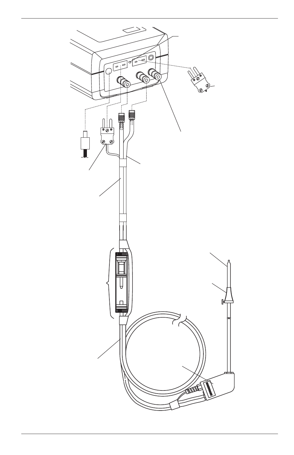
Figure 3-2. connecting the probe to the analyzer, 3 setup – Bacharach Portable Combustion Analyzer 24-9351 User Manual
Page 15
Instruction 24-9351
PCA
Figure 3-2. Connecting the Probe to the Analyzer
3-3
Setup
GAS
RESET
POW
ER
Draft Hose
Flue Gas
Hose
Flue Gas
Thermocouple
Room Air /
Primary Air
Thermocouple
(Optional)
Power Supply
110V/60Hz
230V/50Hz
(Optional)
T-STACK
T-AI
R
Reset Button
Water
Trap / Filter
Assembly
Probe Tube
Adjustable
Probe Stop
Flue
Gas
Hose
Probe
Handle
Pressure Reference
Port (Used in the
Measurement of
Differential Pressure)