Ssembly – Broilmaster PCB1-2 User Manual
Page 9
B101586-4-0112
Page 9
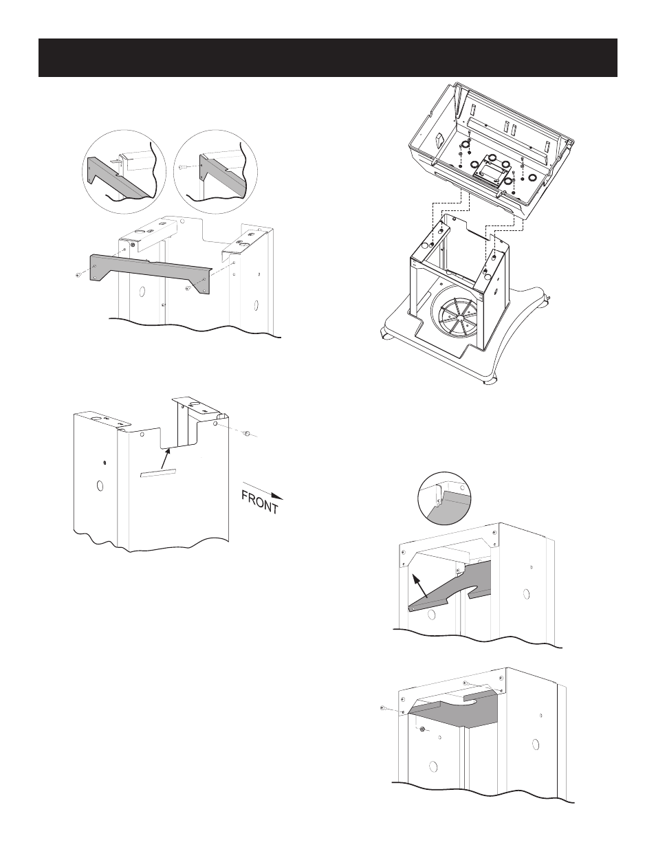
5. Attach Rear Brace to the Left and Right Side Assemblies with
two 1/4-20 x 3/4” Phillips Truss Head screws and 1/4-20 Hex
nuts. See Figure 5. Important: Make sure the brace goes in
the cutout of the support bracket.
Figure 5
6. Insert bushing in the front panel on the right for P and H series
and on the left for R and T series grills. Install rubber guard
over cart cut out. See Figure 6.
Figure 6
Note: Bushing is used to protect the ignitor wires from
rubbing on the front panel when they are in place.
Note: Ignitor wires must go through the bushing before grill
head is fully installed.
7. Secure the grill head to the cart using four 1/4-20 x 3/4” Hex
Head Bolts and 1/4 x 5/8 Flat Washers. See Figure 7.
Note:
To ease assembly, you may wish to install the ignitor as
shown in your Broilmaster
®
grill manual before attaching
the grill to the cart.
Figure 7
8. Attach the Heat Shield to the Left and Right side assemblies
with two 1/4-20 x 3/4 Phillips Truss Head screws and 1/4-20
Hex nuts. Make sure shield is resting on the cutout provided
in the side panels before tightening the screws and nuts. See
Figures 8 and 9. Note: Grill head removed for clarity.
Figure 8
Figure 9
C
Art
A
SSEmbly