Xenyx 1222fx, Control elements and connectors – Behringer XENYX 1222FX User Manual
Page 6
6
XENYX 1222FX
+
The block diagram supplied with the mixing console
gives you an overview of the connections between
the inputs and outputs, as well as the associated
switches and controls.
For the moment, just try and trace the signal path from the
microphone input to the MON SEND connector. Dont be put off
by the huge range of possibilities; its easier than you think! If you
look at the overview of the controls at the same time, youll be
able to quickly familiarize yourself with your mixing console and
youll soon be making the most of all its many possibilities.
1.3 Before you get started
1.3.1 Shipment
Your mixing console was carefully packed in the factory to
guarantee safe transport. Nevertheless, we recommend that
you carefully examine the packaging and its contents for any
signs of physical damage, which may have occurred during
transit.
+
If the unit is damaged, please do NOT return it to us,
but notify your dealer and the shipping company
immediately, otherwise claims for damage or
replacement may not be granted.
1.3.2 Initial operation
Be sure that there is enough space around the unit for cooling
purposes and to avoid over-heating. Please do not place your
mixing console on high-temperature devices such as radiators
or power amps. The console is connected to the mains via the
supplied power cable. The console meets the required safety
standards. Blown fuses must only be replaced by fuses of the
same type and rating.
+
Please note that all units must be properly
grounded. For your own safety, you should never
remove any ground connectors from electrical
devices or power cables, or render them in-
operative.
+
Please ensure that only qualified people install and
operate the mixing console. During installation and
operation, the user must have sufficient electrical
contact to earth, otherwise electrostatic discharges
might affect the operation of the unit.
1.3.3 Online registration
Please do remember to register your new BEHRINGER
equipment right after your purchase by visiting
www.behringer.com (alternatively www.behringer.de) and
kindly read the terms and conditions of our warranty carefully.
Should your BEHRINGER product malfunction, our goal is to
have it repaired as quickly as possible. To arrange for warranty
service, please contact the retailer from whom the equipment
was purchased. Should your BEHRINGER dealer not be located
in your vicinity, you may directly contact one of our subsidiaries.
Corresponding contact information is included in the original
equipment packaging (Global Contact Information/European
Contact Information). Should your country not be listed, please
contact the distributor nearest you. A list of distributors can be
found in the support area of our website (www.behringer.com).
Registering your purchase and equipment with us helps us
process your repair claims quicker and more efficiently.
Thank you for your cooperation!
2. CONTROL ELEMENTS AND
CONNECTORS
This chapter describes the various control elements of your
mixing console. All controls, switches and connectors will be
discussed in detail.
2.1 Mono channels
2.1.1 Microphone and line inputs
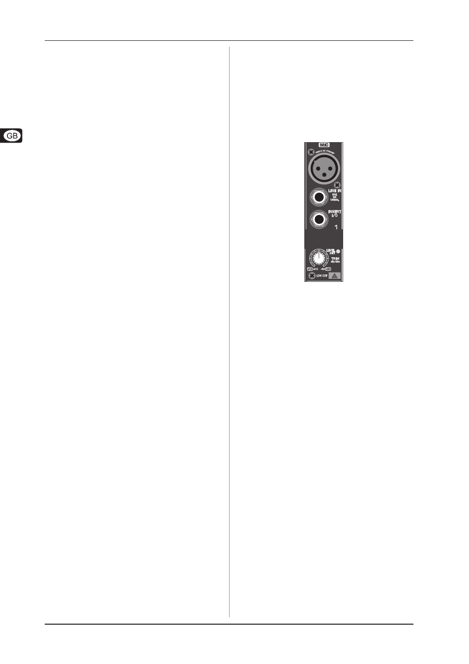
Fig. 2.1: Connectors and controls of mic/line inputs
MIC
Each mono input channel offers a balanced microphone input
via the XLR connector and also features switchable +48 V
phantom power supply for condenser microphones. The XENYX
preamps provide undistorted and noise-free gain as is typically
known only from costly outboard preamps.
+
Please mute your playback system before you
activate the phantom power supply to prevent
switch-on thumps being directed to your loud-
speakers. Please also note the instructions in
chapter 2.5 Rear view of 1222FX.
LINE IN
Each mono input also features a balanced line input on a 1/4"
connector. Unbalanced devices (mono jacks) can also be
connected to these inputs.
+
Please remember that you can only use either the
microphone or the line input of a channel at any
one time. You can never use both simultaneously!
INSERT
Insert points enable the processing of a signal with dynamic
processors or equalizers. They are sourced pre-fader, pre-EQ
and pre-aux send. Unlike reverb or other effects devices, whose
signals are usually added to the dry signal, dynamic processors
are most effective on the complete signal. In this case, aux send
paths are a less-than-perfect solution. It is better to interrupt the
signal path and insert a dynamic processor and/or equalizer.
After processing, the signal is routed back to the console at
precisely the same point it left. However, the channel signal path
is interrupted only if a plug is inserted into the corresponding jack
(stereo phone plug: tip = signal output; ring = return input). All
mono input channels are equipped with inserts.
Inserts can also be used as pre-EQ direct outputs, without
interrupting the signal path. To this end, you will need a cable
fitted with mono phone plugs on the tape machine or effects
device end, and a bridged stereo phone plug on the console side
(tip and ring connected).
2. CONTROL ELEMENTS AND CONNECTORS