Bryant 395CAV User Manual
Page 2
WARNING:
Improper installation, adjustment, alter-
ation, service, maintenance, or use can cause carbon
monoxide poisoning, explosion, fire, electrical shock, or
other conditions which may cause personal injury or
property damage. Consult a qualified installer, service
agency, local gas supplier, or your distributor or branch
for information or assistance. The qualified installer or
agency must use only factory-authorized and listed kits or
accessories when modifying this product.
For accessory installation details, refer to the applicable instruction
literature.
NOTE:
Remove all shipping brackets and materials before oper-
ating the furnace.
CODES AND STANDARDS
Before installing the furnace in the United States, refer to the
current edition of the NFGC and the NFPA 90B. For copies of the
NFGC and NFPA 90B, contact the National Fire Protection
Association Inc., Batterymarch Park, Quincy, MA 02269; or for
only the NFGC contact the American Gas Association, 400 N.
Capitol St., N.W., Washington DC 20001.
Before installing the furnace in Canada, refer to the NSCNGPIC.
For a copy of the NSCNGPIC, contact Standard Sales, CSA
International, 178 Rexdale Boulevard, Etobicoke (Toronto), On-
tario, M9W 1R3, Canada.
Installation must comply with regulations of serving gas supplier
and local building, heating, plumbing or other codes in effect in the
area in which installation is made. In absence of local building
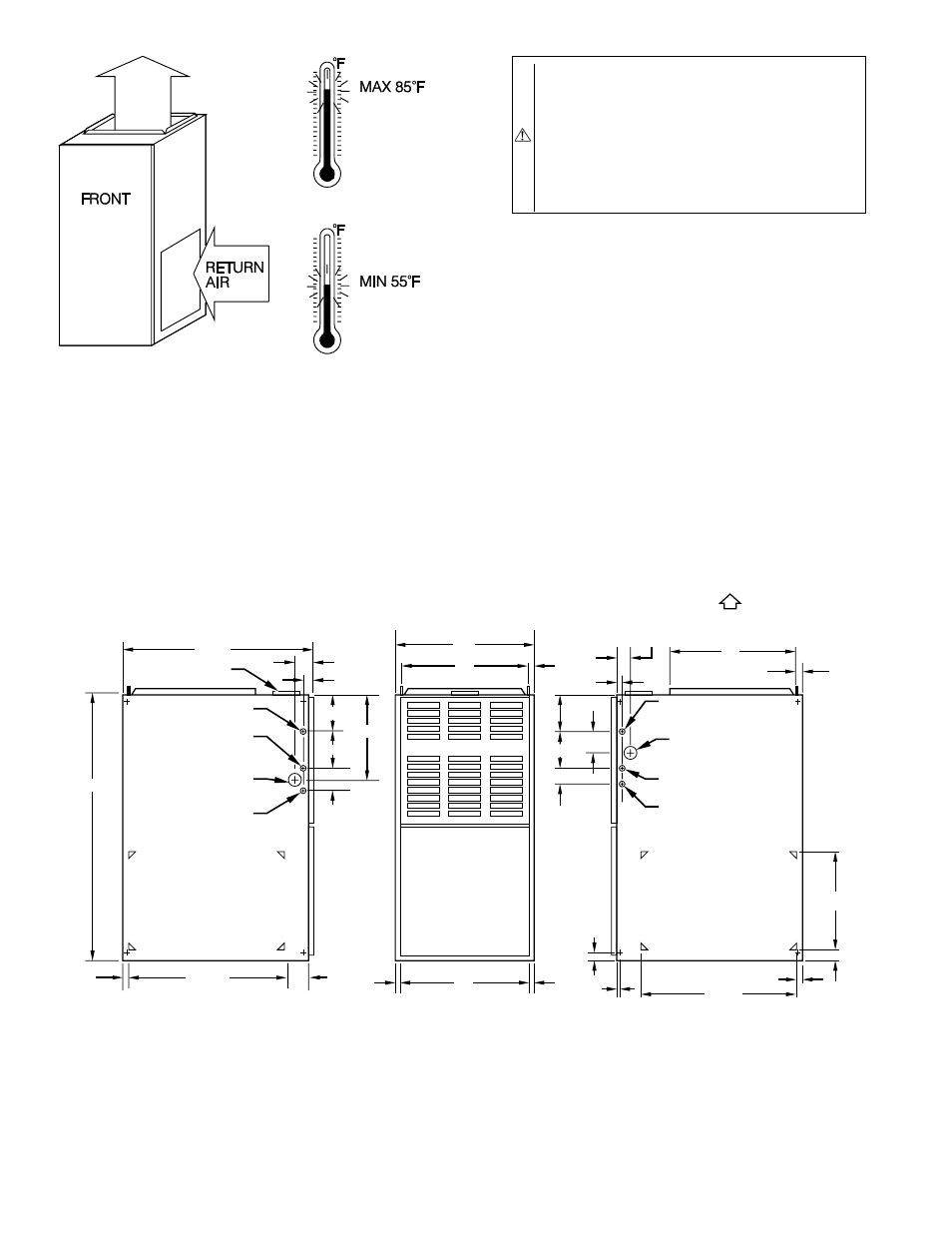
Fig. 1—Dimensional Drawing
A00210
A
D
13
⁄
16
″
E
11
⁄
16
″
11
⁄
16
″
28
1
⁄
2
″
39
7
⁄
8
″
24
5
⁄
16
″
11
⁄
16
″
3
″
2
1
⁄
16
″
1
″
12
5
⁄
16
″
5
3
⁄
8
″
5
13
⁄
16
″
2
3
⁄
8
″
AIR INLET
7
⁄
8
-IN. DIA HOLE
POWER ENTRY
7
⁄
8
-IN. DIA
ACCESSORY
1
3
⁄
4
-IN.
DIA HOLE
GAS ENTRY
1
⁄
2
-IN. DIA HOLE
THERMOSTAT
WIRE ENTRY
SIDE INLET
VENT CONN
1. Two additional
7
⁄
8
-
in. dia holes are located in the top plate.
2. Minimum return-air openings at furnace, based on metal duct. If flex duct is used,
see flex duct manufacturer's recommendations for equivalent diameters.
a. For 800 CFM–16-in. round or 14
1
⁄
2
x 12-in. rectangle.
b. For 1200 CFM–20-in. round or 14
1
⁄
2
x 19
1
⁄
2
-in. rectangle.
c. For 1600 CFM–22-in. round or 14
1
⁄
2
x 23
1
⁄
4
-in. rectangle.
d. For airflow requirements above 1800 CFM, see Air Delivery table in Product Data literature for specific
use of single side inlets. The use of both side inlets, a combination of 1 side and the bottom, or the
bottom only will ensure adequate return air openings for airflow requirements above 1800 CFM.
NOTES:
5
3
⁄
8
″
5
13
⁄
16
″
2
3
⁄
8
″
2
11
⁄
16
″
1
″
2
1
⁄
16
″
19
″
13
⁄
16
″
7
⁄
8
-IN.
DIA
POWER ENTRY
AIRFLOW
OUTLET
1
1
⁄
2
-IN.
DIA
R.H. GAS ENTRY
7
⁄
8
-IN. DIA ACCESSORY
1
⁄
2
-IN. DIA THERMOSTAT
WIRE ENTRY
SIDE INLET
14
1
⁄
2
″
1
″
23
1
⁄
4
″
SIDE RETURN
DUCT LOCATION
1
1
⁄
4
″
TYP 1
″
5
⁄
8
″
TYP
A93042
—2—