V.11/x.21 link pinouts – Black Box LR5100A-T User Manual
Page 91
Interface Pinouts
83
V.11/X.21 Link Pinouts
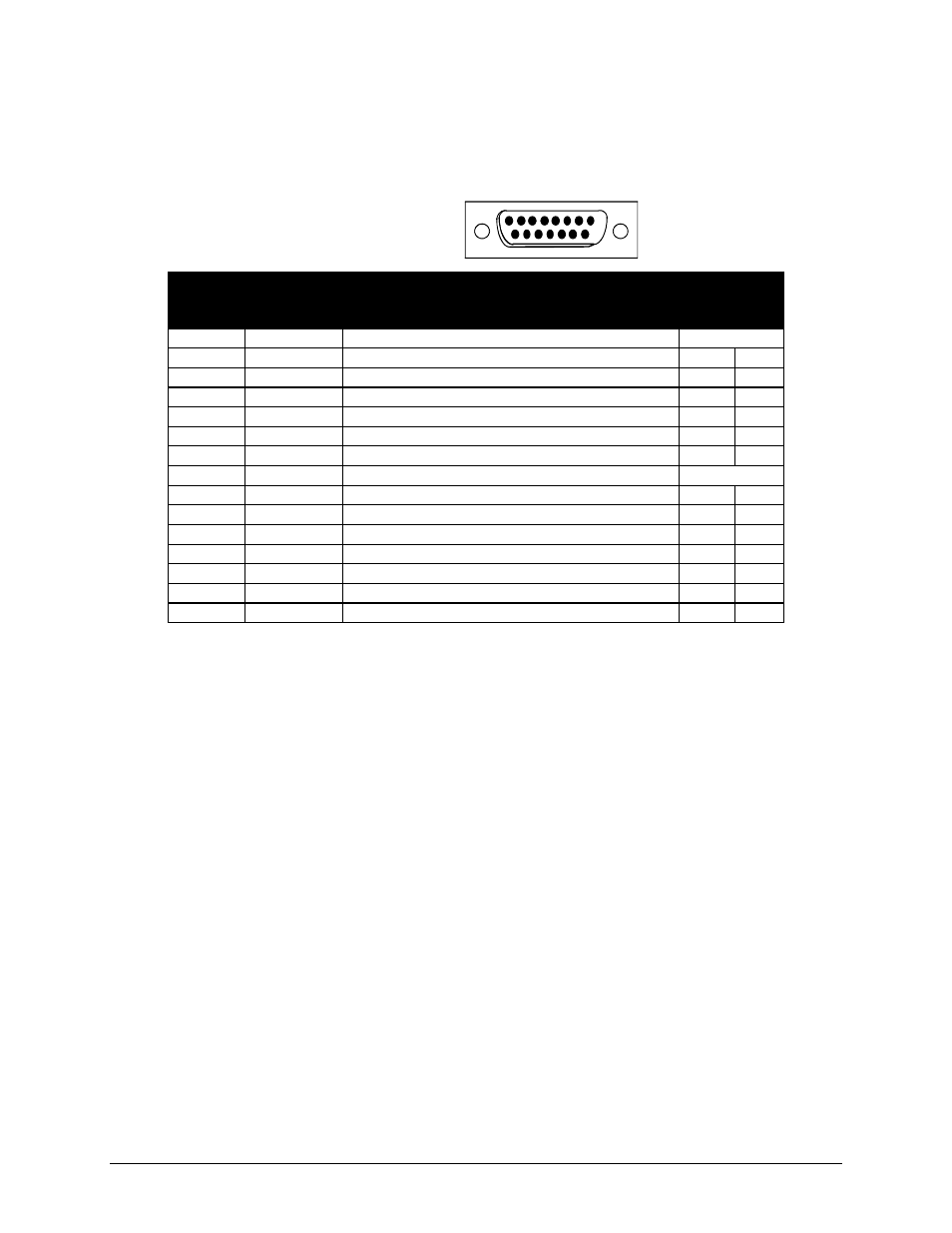
The connector shown here and pinouts described here correspond to the connector labeled
“V.11/x.21” on the back of the unit.
DB15 Female DTE
1
8
9
15
Contact
Number
X.21
Circuits
Reference
Circuit
Name
Direction
To From
DCE DCE
1
Protective Ground
NA
2
T (A)
Transmitted Data (A)
X
3
C (A)
Control (A)
X
4
R (A)
Received Data (A)
X
5
I (A)
Indication (A)
X
6
S (A)
Signal Element Timing (A)
X
7
----------
8
Ground
Signal Ground
NA
9
T (B)
Transmitted Data (B)
X
10
C (B)
Control (B)
X
11
R (B)
Received Data (B)
X
12
I (B)
Indication (B)
X
13
S (B)
Signal Element Timing (B)
X
14
----------
15
----------
Figure D-6 V.11/x.21 Link Pinouts
The connecting cable must be a shielded cable.
Circuits which are paired (contain an (A) and (B) reference) should be connected to
twisted pairs within the connecting cable.
NOTE For U.K. Approval:
The connecting cable may be any length between 0 and 5M. Each end must be terminated in
a male 15 pin X.21 connector as defined in ISO-4903 1989, but one end of the cable must
have UNC-4-40 screws and the other end must have M3 screws.