Prior to installation, Electrical connection – Neff D4654X0 User Manual
Page 14
14
Prior to installation
2.
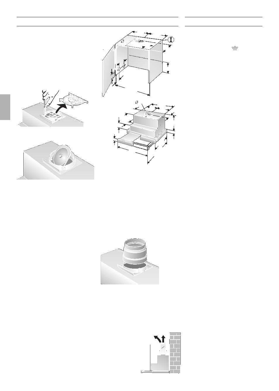
Insert the one-way flap into the bearing
apertures on the air-pipe connector.
If the exhaust air is going to be
discharged into the open,
a telescopic
wall box should be fitted into the outside
wall.
For optimum extractor hood efficiency:
q
Short, smooth air exhaust pipe.
q
As few bends in the pipe as possible.
q
Diameter of pipe to be as large as
possible (ideal is l 120 mm ) and no
tight bends in pipe.
If long, rough exhaust-air pipes,
many pipe bends or smaller pipe
diameters are used, the air extraction
rate will no longer be at an optimum
level and there will be an increase in
noise.
21
32
600
17
0
133
287
313
195
250
q Round pipes:
We recommend
Internal diameter at least. 120 mm.
q Flact ducts
must have an internal
cross-section that equates to that of
round pipes with a 100/120 mm internal
diameter
There should be no sharp bends.
l
100 mm approx.
0
78 cm
2
l
120 mm approx. 113 cm
2
If pipes have different diameters:
q
Insert sealing strip.
q For exhaust-air mode,
ensure that
there is an adequate supply of fresh air.
Exhaust air flows upwards:
q
Cut a hole in the top of the wall cupbo-
ard, including a groove for the mains
cable.
– Template
O
I
lis enclosed –.
mind. 30
115
80
18
5
120
512
243
269
90
250
32
2
8
0
598
2
8
0
-4
4
3
Connecting the l 120 mm
exhaust-air pipe:
q
Cut out the protective grid in the air
outlet.
Circulating-air mode
q
With activated carbon filter if exhaust-air
mode is not possible.
ṇ
The complete
installation set can
be obtained from
specialist
outlets.
The corresponding
accessory numbers
can be found at the
end of these opera-
ting instructions.
O
100
120
For operating in exhaust-air mode,
a
one-way flap should be mounted inside the
extractor hood unless there is already one
fitted in the outlet duct or wall ventilation
box.
If no one-way flap was enclosed with the
hood, it can be obtained from a specialist
retailer (see section on optional accessories
in the user instructions).
Installing the one-way flap:
1.
Cut out the protective grid in the air-pipe
connector.
Exhaust flows straight out at the
back:
– inside the wall cupboard –.
q
Cut a hole in the rear panel of the wall
cupboard, including a groove for the
mains cable.
Connecting the l 100 mm
exhaust-air pipe:
q
Cut out the protective grid in the air
outlet.
q
Attach the reducing connector (enclosed
or can be obtained from specialist
retailers) to the air outlet.
Electrical connection
This is what you have to do:
1.
Connect the green and yellow (Earth)
wire to the terminal in the plug marked
‘E’ or with the symbol ( ), or
coloured green or green and yellow.
2.
Connect the blue (Neutral) wire to the
terminal in the plug marked ‘N’ or
coloured black.
3.
Connect the brown (Live) wire to the
terminal marked ‘L’, or coloured red.
The extractor hood
may only be
connected to an earthed socket that has
been installed according to the relevant
regulations. If possible, site the earthed
socket directly above the wall cupboard or
in its immediate vicinity.
Electrical data:
Are to be found on the name plate inside
the appliance after removal of the filter
frame.
ṇ
Before undertaking any repairs,
always disconnect the extractor hood from
the electricity supply.
Length of the connecting cable: 1.30 m.
If it is necessary to wire the extractor
hood directly into the mains:
The extractor hood should only be
connected to the electricity supply by a
properly qualified electrician.
A separator must be installed in the
household circuit. A suitable separator is a
switch that has a contact gap of more than
3 mm and interrupts all poles. Such
devices include circuit breakers and
contactors.
This extractor hood corresponds to EC
regulations concerning RF interference
suppression.