Bryant GAS-FIRED INDUCED-COMBUSTION FURNACES 373LAV User Manual
Page 3
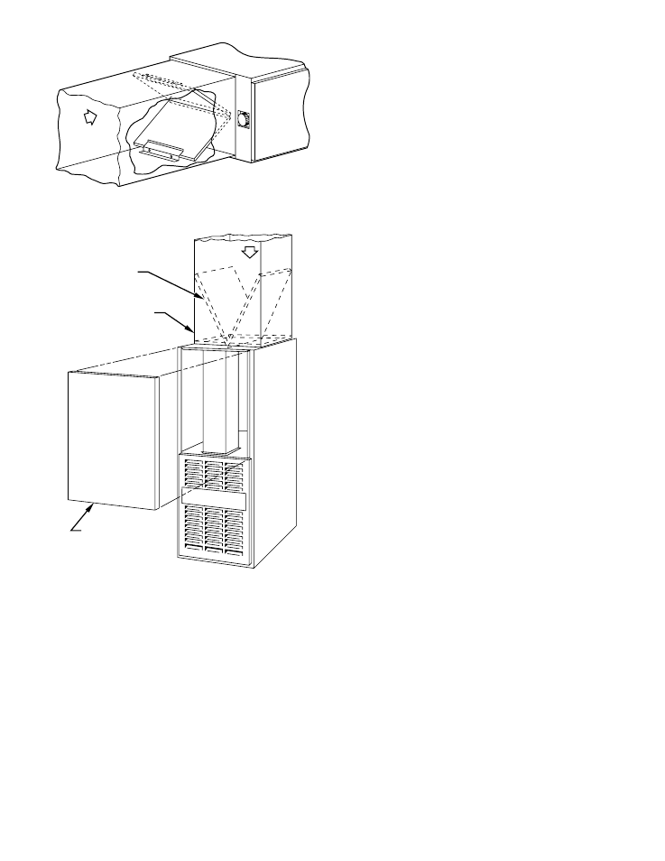
1. Downflow/Horizontal
Each furnace requires 2 filters which are installed in the
return-air duct. (See Fig. 4 and 5.) To remove filters for
cleaning or replacement, proceed as follows:
a. Disconnect electrical power before removing blower
access door.
b. Remove screw from front of door and remove blower
access door.
c. Reach up behind top plate, tilt filters toward center of
return-air plenum, remove filters, and clean as needed.
Replace if torn.
d. Furnaces are equipped with permanent, washable filters.
Clean filters with tap water. Spray water through filter in
opposite direction of airflow.
e. Rinse and let dry. Oiling or coating of filters is not
recommended or required.
f. Reinstall filters.
g. Replace blower access door.
h. Restore electrical power to furnace.
2. Upflow
Each furnace requires 1 or 2 filters which are installed in the
blower compartment. (See Fig. 6.) To remove filters for
cleaning or replacement, proceed as follows:
a. Disconnect electrical power before removing access
doors.
b. Remove blower and control access doors.
c. Release filter retainer from clip at front of furnace
casing. (See Fig. 6.) For side return, clips may be used on
either or both sides of the furnace.
d. Slide filter(s) out.
e. Furnaces are equipped with permanent, washable filters.
Clean filters with tap water. Spray water through filter in
opposite direction of airflow.
f. Rinse and let dry. Oiling or coating of filter is not
recommended or required.
g. Reinstall filter(s).
h. Replace blower and control access doors.
i. Restore electrical power to furnace.
B.
Blower Motor and Wheel
The following steps should be performed by a qualified service
technician.
To ensure long life, economy, and high efficiency, clean accumu-
lated dirt and grease from blower wheel and motor annually.
The inducer and blower motors are pre-lubricated and require no
additional lubrication. These motors can be identified by the
absence of oil ports on each end of the motor.
Clean blower motor and wheel as follows:
1. Turn off electrical supply to furnace.
2. Remove
2
screws
from
blower
access
door
(downflow/horizontal furnace only) and remove blower
access door.
3. Downflow only.
a. Disconnect vent connector from furnace flue collar. (See
Fig. 7.)
b. Remove internal vent pipe enclosure cover.
c. Disconnect and remove short piece of vent pipe from
within furnace.
d. Disconnect and remove vent pipe enclosure. Push bot-
tom side backward to release tabs.
NOTE:
Vent pipe is SCREWED and RTV sealed to relief box.
4. Disconnect blower leads from furnace control. Note wire
color and location for reassembly. Also, disconnect auxil-
iary limit switch leads (downflow only, if present).
All other factory wires can be left connected, but field
thermostat connections may need to be disconnected de-
pending on their length and routing.
5. Remove 2 screws securing control and transformer support
to furnace.
6. Hang control and transformer support to front of furnace
casing.
7. Remove screws holding blower assembly to blower deck
and slide blower assembly out of furnace.
8. Clean blower wheel and motor using a vacuum with soft
brush attachment. Do not remove or disturb balance weights
(clips) on blower wheel blades. The blower wheel should
not be dropped or bent as balance will be affected.
Fig. 4—Horizontal Filter Arrangement
A94307
,
,,,
,,,,,
,,,,,,
,,,,,
,,
,,,
,,,
AIRFLOW
Fig. 5—Downflow Filter Arrangement
A88486
RETURN-AIR
PLENUM
,,,,
,,,,
,,,,
,,,,
,,,,
,,,,
,,,,
,,,,
,,,,
AIRFLOW
ACCESS DOOR
INSTALLATION
POSITION
OF FILTERS
—3—