Power amp (sold separately), Connections – Pioneer DEH-80PRS User Manual
Page 3
e ISO connector
In some vehicles, the ISO connector may be
divided into two. In this case, be sure to con-
nect to both connectors.
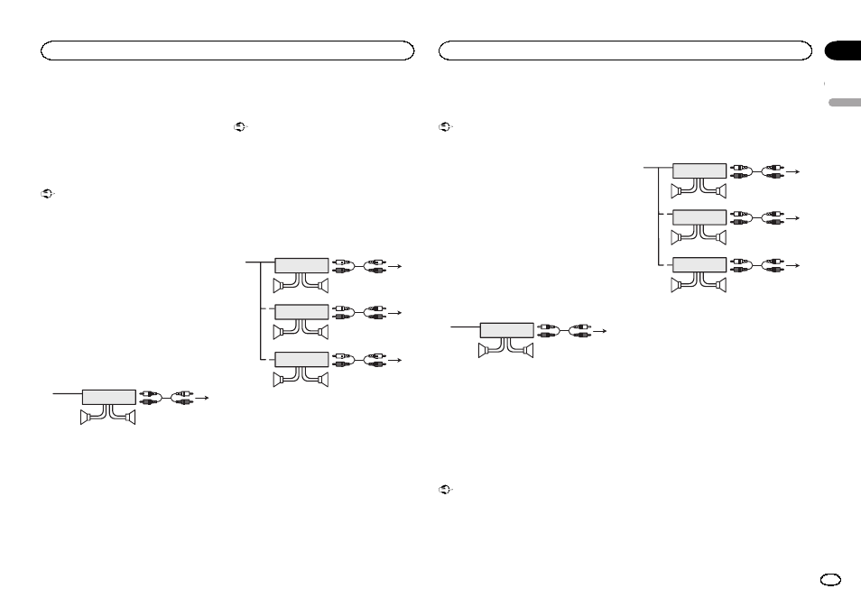
Power amp (sold separately)
Standard mode with internal amp
Important
! Change the DSP switch to standard mode
(STD).
For more details on change settings, refer to
the operation manual or Switching the DSP
setting mode on this page.
! The following signals are output from the
speaker leads when this connection is in
use.
White: Front left
+
White/black: Front left
*
Gray: Front right
+
Gray/black: Front right
*
Green: Rear left
+
Green/black: Rear left
*
Violet: Rear right
+
Violet/black: Rear right
*
1
3
2
4
5
5
1 System remote control
Connect to Blue/white cable.
2 Power amp (sold separately)
3 Connect with RCA cable (sold separately)
4 To subwoofer output
5 Subwoofer
Standard mode without internal
amp
Important
! Change the DSP switch to standard mode
(STD).
For more details on change settings, refer to
the operation manual or Switching the DSP
setting mode on this page.
! If using this system, we recommend that this
unit
’s internal amp is turned off.
For details, refer to the operation manual.
! The speaker leads are not used when this
connection is in use.
1
1
3
2
4
3
8
5
5
3
2
6
7
7
9
9
2
1
1 System remote control
Connect to Blue/white cable.
2 Power amp (sold separately)
3 Connect with RCA cable (sold separately)
4 To Rear output
5 Rear speaker
6 To Front output
7 Front speaker
8 To subwoofer output
9 Subwoofer
3-way network mode with
internal amp
Important
! Change the DSP switch to 3-way network
mode (NW).
For more details on change settings, refer to
the operation manual or Switching the DSP
setting mode on this page.
! The following signals are output from the
speaker leads when this connection is in
use.
White: Middle range left
+
White/black: Middle range left
*
Gray: Middle range right
+
Gray/black: Middle range right
*
Green: High range left
+
Green/black: High range left
*
Violet: High range right
+
Violet/black: High range right
*
1
3
2
4
5
5
1 System remote control
Connect to Blue/white cable.
2 Power amp (sold separately)
3 Connect with RCA cable (sold separately)
4 To low range output
5 Low range speaker
3-way network mode without
internal amp
Important
! Change the DSP switch to 3-way network
mode (NW).
For more details on change settings, refer to
the operation manual or Switching the DSP
setting mode on this page.
! If using this system, we recommend that this
unit
’s internal amp is turned off.
For details, refer to the operation manual.
! The speaker leads are not used when this
connection is in use.
1
1
3
2
4
3
8
5
5
3
2
6
7
7
9
9
2
1
1 System remote control
Connect to Blue/white cable.
2 Power amp (sold separately)
3 Connect with RCA cable (sold separately)
4 To high range output
5 High range speaker
6 To middle range output
7 Middle range speaker
8 To low range output
9 Low range speaker
Switching the DSP setting mode
This unit features two operation modes: the 3-
way network mode (NW) and the standard mode
(STD). You can switch between modes as de-
sired. Initially, the DSP setting is set to the
standard mode (STD).
! After switching, reset the microprocessor.
English
Connections
3
Section
Connections
En
01