Starting and stopping the miter saw, Locking the switch in the “off” position, Rotating the table for miter cutting – Black & Decker BT2000L User Manual
Page 50
50
STARTING AND STOPPING THE MITER SAW
The torque developed during braking may loosen the arbor screw. Check the arbor screw
periodically and tighten, if necessary.
LOCKING THE SWITCH IN THE “OFF” POSITION
When the machine is not in use, the
switch should be locked in the “OFF”
position, using a padlock (B) Fig. 10
with a 3/16" diameter shackle to
prevent unauthorized use.
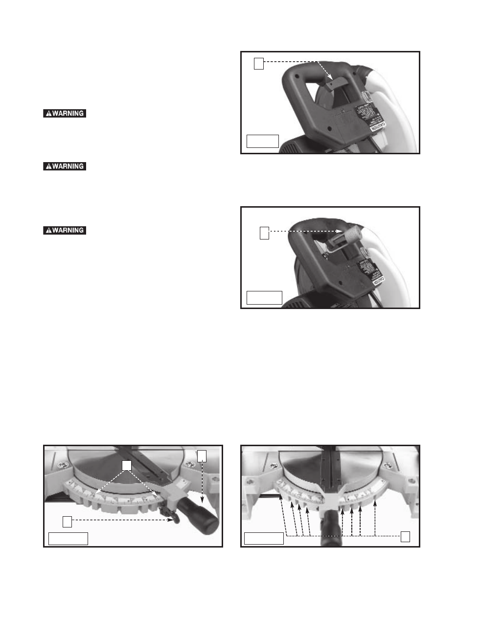
To start the miter saw, depress the switch trigger (A)
Fig. 9. To stop the miter saw, release the switch trigger.
This saw is equipped with an automatic electric blade
brake. As soon as the switch trigger (A) Fig. 9 is
released, the electric brake is activated and stops the
blade in seconds.
A
Fig. 9
B
Fig. 10
A turning saw blade can be
dangerous. After completing the cut,
release the switch trigger (A) Fig. 9 to
activate the blade brake. Keep the
cuttinghead down until the blade has
come to a complete stop.
ROTATING THE TABLE FOR MITER CUTTING
Your miter saw will cut any angle from a straight 90° cut to 47° right and left. Loosen the lock handle (A) Fig. 11 one
or two turns, depress the index lever (B), and move the control arm to the desired angle.
TIGHTEN THE LOCK
HANDLE (A).
The miter saw is equipped with positive stops at the 0°, 15.0°, 22.5°,31.62° and 45° right and left positions. Loosen
the lock handle (A) Fig. 11, and move the control arm until the bottom of the index lever (B) engages into one of the
positive stops (C) Fig. 12.
TIGHTEN THE LOCK HANDLE (A) Fig. 11. To disengage the positive stop, depress the
index lever (B).
In addition, an indicator (D) Fig. 11 is provided on the miter scale at the 33.9° right and left miter positions for cutting
crown moulding. (Refer to the
“CUTTING CROWN MOULDING” section of this manual).
IMPORTANT: Always tighten the lock handle (A) Fig. 11 before cutting.
B
A
C
Fig. 11
Fig. 12
D