Installation – Pioneer MVH-X560BT User Manual
Page 16
Black plate (16,1)
9 Blue/white
The pin position of the ISO connector will dif-
fer depending on the type of vehicle. Connect
9 and b when Pin 5 is an antenna control
type. In another type of vehicle, never con-
nect
9 and b.
a Blue/white
Connect to system control terminal of the
power amp (max. 300 mA 12 V DC).
b Blue/white
Connect to auto-antenna relay control termi-
nal (max. 300 mA 12 V DC).
c Speaker leads
White: Front left
+
White/black: Front left
*
Gray: Front right
+
Gray/black: Front right
*
Green: Rear left
+ or subwoofer +
Green/black: Rear left
* or subwoofer *
Violet: Rear right
+ or subwoofer +
Violet/black: Rear right
* or subwoofer *
d ISO connector
In some vehicles, the ISO connector may be
divided into two. In this case, be sure to con-
nect to both connectors.
Notes
! Change the initial menu of this unit. Refer to
REAR-SP (rear output setting) on page 14.
The subwoofer output of this unit is monau-
ral.
! When using a subwoofer of 70 W (2 W), be
sure to connect the subwoofer to the violet
and violet/black leads of this unit. Do not
connect anything to the green and green/
black leads.
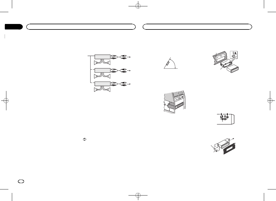
Power amp (sold separately)
Perform these connections when using the op-
tional amplifier.
1
1
3
2
4
5
5
3
2
6
7
7
1
3
2
8
9
9
1 System remote control
Connect to Blue/white cable.
2 Power amp (sold separately)
3 Connect with RCA cables (sold separately)
4 To Rear output
5 Rear speaker
6 To Front output
7 Front speaker
8 To Subwoofer output
9 Subwoofer
Installation
Important
! Check all connections and systems before
final installation.
! Do not use unauthorized parts as this may
cause malfunctions.
! Consult your dealer if installation requires
drilling of holes or other modifications to the
vehicle.
! Do not install this unit where:
— it may interfere with operation of the vehicle.
— it may cause injury to a passenger as a result
of a sudden stop.
! The semiconductor laser will be damaged if
it overheats. Install this unit away from hot
places such as near the heater outlet.
! Optimum performance is obtained when the
unit is installed at an angle of less than 60°.
60°
! When installing, to ensure proper heat dis-
persal when using this unit, make sure you
leave ample space behind the rear panel and
wrap any loose cables so they are not block-
ing the vents.
5cm
cm
Leave ample
space
5 cm
5 cm
DIN front/rear mount
This unit can be properly installed using either
front-mount or rear-mount installation.
Use commercially available parts when instal-
ling.
DIN Front-mount
1
Insert the mounting sleeve into the dash-
board.
For installation in shallow spaces, use the sup-
plied mounting sleeve. If there is enough space,
use the mounting sleeve that came with the ve-
hicle.
2
Secure the mounting sleeve by using a
screwdriver to bend the metal tabs (90°) into
place.
1
2
1 Dashboard
2 Mounting sleeve
# Make sure that the unit is installed securely in
place. An unstable installation may cause skipping
or other malfunctions.
DIN Rear-mount
1
Line up the holes on the mounting brack-
et with the holes on the sides of the unit to
attach the bracket.
2
Screw in one screw on each side to hold
the unit in place.
1
2
3
1 Tapping screw (5 mm × 8 mm)
2 Mounting bracket
3 Dashboard or console
Installation
16
Section
Installation
En
03