Ultra-curve pro structure – Behringer DSP8024 User Manual
Page 26
26
ULTRA-CURVE PRO DSP8024
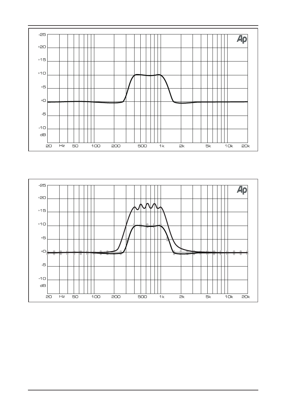
Fig. 4.2: ULTRA-CURVE PRO with “true response”
Fig. 4.3: Combination of 4.1 and 4.2—with the fader positions added
5. ULTRA-CURVE PRO STRUCTURE
5.1 Hardware
The analog input signals first pass through the electronic balancing amplifier and are then fed to the A/D converters.
Here they are converted into a time division multiplex digital signal suitable for the DSPs. The reference microphone
input feeds a balanced amplifier, which raises the signal level by 20 dB. The signal is then sent through a switch
5. ULTRA-CURVE PRO STRUCTURE
See also other documents in the category Behringer Receivers and Amplifiers:
- TUBE ULTRAGAIN MIC100 (19 pages)
- iNuke NU6000DSP (22 pages)
- BA410 (9 pages)
- DEQ1024 (14 pages)
- MDX4400 (25 pages)
- 000-Watt Stereo Power Amplifier EP2000 (14 pages)
- UB2442FX-PRO (16 pages)
- PA Amplifiers Europower EPQ 304 (9 pages)
- ULTRA-DIDI20 (10 pages)
- BXL450 (10 pages)
- B1220 PRO (10 pages)
- VMX100 (11 pages)
- ACX900 (11 pages)
- ACX1000 (17 pages)
- FBQ6200/FBQ3102/FBQ1502 (14 pages)
- AC108 (9 pages)
- T1953 (23 pages)
- BB810 (9 pages)
- MiniFBQ FBQ800 (17 pages)
- MX882 (16 pages)
- Super-X Pro CX2310 (13 pages)
- V-AMPIRE LX1200H (19 pages)
- UB1204-PRO (13 pages)
- MIC200 (12 pages)
- Europower EP1500 (14 pages)
- Europower EXP2800 (15 pages)
- UB1832FX-PRO (16 pages)
- UB1622FX-PRO (3 pages)
- PRO MIXER (11 pages)
- XENYX 1222FX (15 pages)
- BCD2000 (16 pages)
- gm108 (10 pages)
- A500 (10 pages)
- AT108 (8 pages)
- DSP1200P (42 pages)
- DI800 (8 pages)
- BLUES OVERDRIVE BO100 (2 pages)
- MINIAMP AMP800 (13 pages)
- BG412V (3 pages)
- Europower EP1500 (4 pages)
- BA115 (9 pages)
- HA4400 (16 pages)
- 1002FX (12 pages)
- BASS V-AMP (20 pages)