Connection requirements, Connection instructions, Atural – Broilmaster DPSBSS-1 User Manual
Page 12: Onnection
B100539-2-0610
Page 12
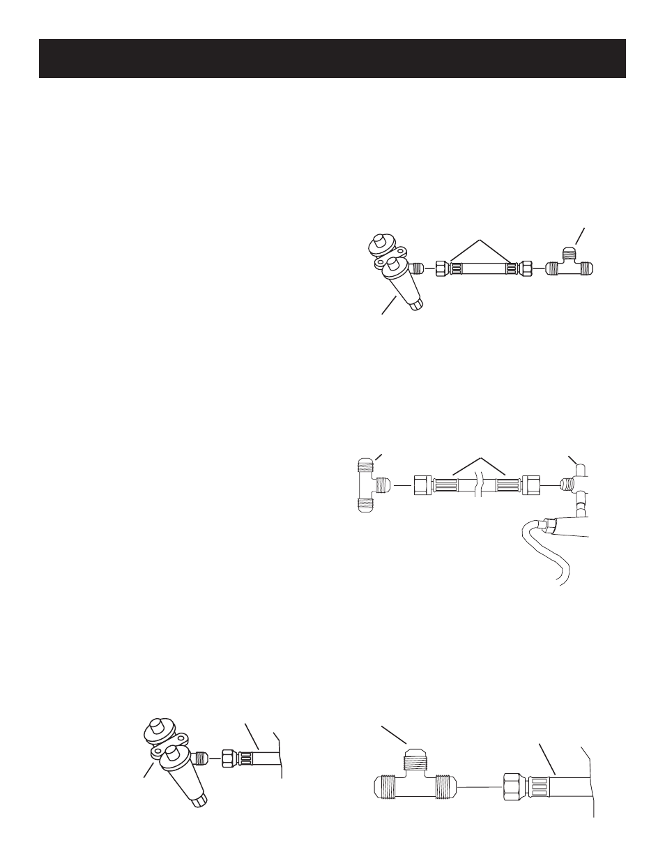
Attach one end of the 10" S/S flex line (18) to the end
of the grill’s gas valve.
Attach the other end of the S/S flex line to the brass
“tee” (17). F
igure
14.
The grill’s natural gas supply line valve installed by your
gas company must be turned to OFF.
i
MPOrtant
: t
he
GaS
SuPPly
line
MuSt
have
a
Shut
-
Off
valve
inSide
the
wall
. c
Ontact
yOur
lOcal
GaS
cOMPany
fOr
directiOnS
.
Disconnect the copper gas supply line from the gas
valve located under the grill’s control panel. F
igure
13.
Attach one end of the 34" S/S flex line (19) to the end
of the side burner valve (14).
Attach the remaining end of the S/S flex line to the end
of the “tee” (17) connector. F
igure
15.
f
iGure
13
Grill Gas Valve
Gas Supply Line
Attach the copper gas supply line to the brass “tee”
(17). Use two adjustable wrenches to tighten the joint.
F
igure
16.
“Tee” (17)
Connection Requirements
Installation must conform to local codes or, in the ab-
sence of local codes, with the National Fuel Gas Code,
ANSI Z223.1. In Canada, installation shall be in ac-
cordance with CAN/CGA-B149.2 Propane Installation
Code, or CAN/CGA-B149.1 Natural Gas Installation
Code, and local codes where applicable. Contact your
local gas company for code regulations, recommended
procedures, and the installation of your grill’s gas sup-
ply line.
Broilmaster
®
gas grills and side burners are not equipped
with pressure regulators. Your gas grill operates at a
manifold pressure of seven (7") inches water column.
Connect cart mounted natural gas grills to a pre-in-
stalled gas supply line using the twelve (12') foot flexible
hose and quick disconnect kit supplied or specified by
the manufacturer.
c
autiOn
: t
he
Grill
and
itS
individual
ShutOff
valve
MuSt
Be
diScOnnected
frOM
the
GaS
SuPPly
PiPinG
SySteM
durinG
any
SySteM
PreSSure
teStinG
at
teSt
PreSSureS
in
exceSS
Of
1/2
PSiG.
c
autiOn
: t
he
Grill
MuSt
Be
iSOlated
frOM
the
GaS
SuPPly
PiPinG
SySteM
By
clOSinG
itS
individual
Manual
ShutOff
valve
durinG
any
PreSSure
teStinG
Of
the
GaS
SuPPly
PiPinG
SySteM
at
teSt
PreSSureS
equal
tO
Or
leSS
than
1/2 PSiG.
Connection Instructions
f
iGure
16
“Tee” (17)
Gas Supply Line
f
iGure
14
Grill Gas Valve
7" S/S flex line (18)
f
iGure
15
34" S/S flex line (19)
17
14
N
ATURAL
G
AS
C
ONNECTION