Am pli fier gain mea sure ment 4-24, Set ting the markers 4-24, Amplifier gain measurement -24 – Anritsu S251B User Manual
Page 70: Setting the markers -24, Amplifier gain measurement, Setting the markers, Step 14. press the, Soft key to select the m1 marker function, Chapter 4 measurements, Marker
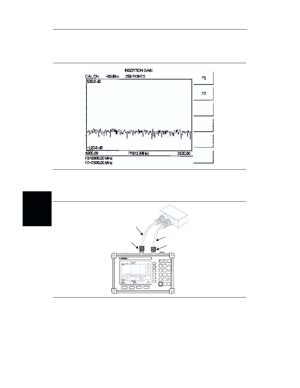
Amplifier Gain Measurement
Step 12. Disconnect the 7/16(f) adapter. The resulting display should be similar to Figure
Step 13. Connect the amplifier to the test port extension cables as shown in Figure 4-20.
Setting the Markers
Step 14. Press the
MARKER
key to call up the Markers menu.
Step 15. Press the
M1
soft key to select the M1 marker function.
4-24
Chapter 4 Measurements
Figure 4-19.
Measurement Display Before Amplifier Connection
Ant
PCS
Amp
Tx\RF
HOLD
RUN
START
CAL
AUTO
SCALE
SAVE
SETUP
RECALL
SETUP
LIMIT
MARKER
SAVE
DISPLAY
RECALL
DISPLAY
MODE
FREQ/DIST
AMPLITUDE
SWEEP
SYS
ENTER
CLEAR
ESCAPE
ON
OFF
/
1
2
4
5
6
7
8
9
0
3
+
-
.
Site Master S251B
625.0
2500.0
1384.45 MHz
2096.66 MHz
RF OUT TEST PORT
RF IN TEST PORT
TEST PORT CABLE
(OPTIONAL)
TEST PORT CABLE
(OPTIONAL)
Figure 4-20.
Amplifier Gain Measurement Setup