AOC P/N : 41A50-144 User Manual
Page 17
16
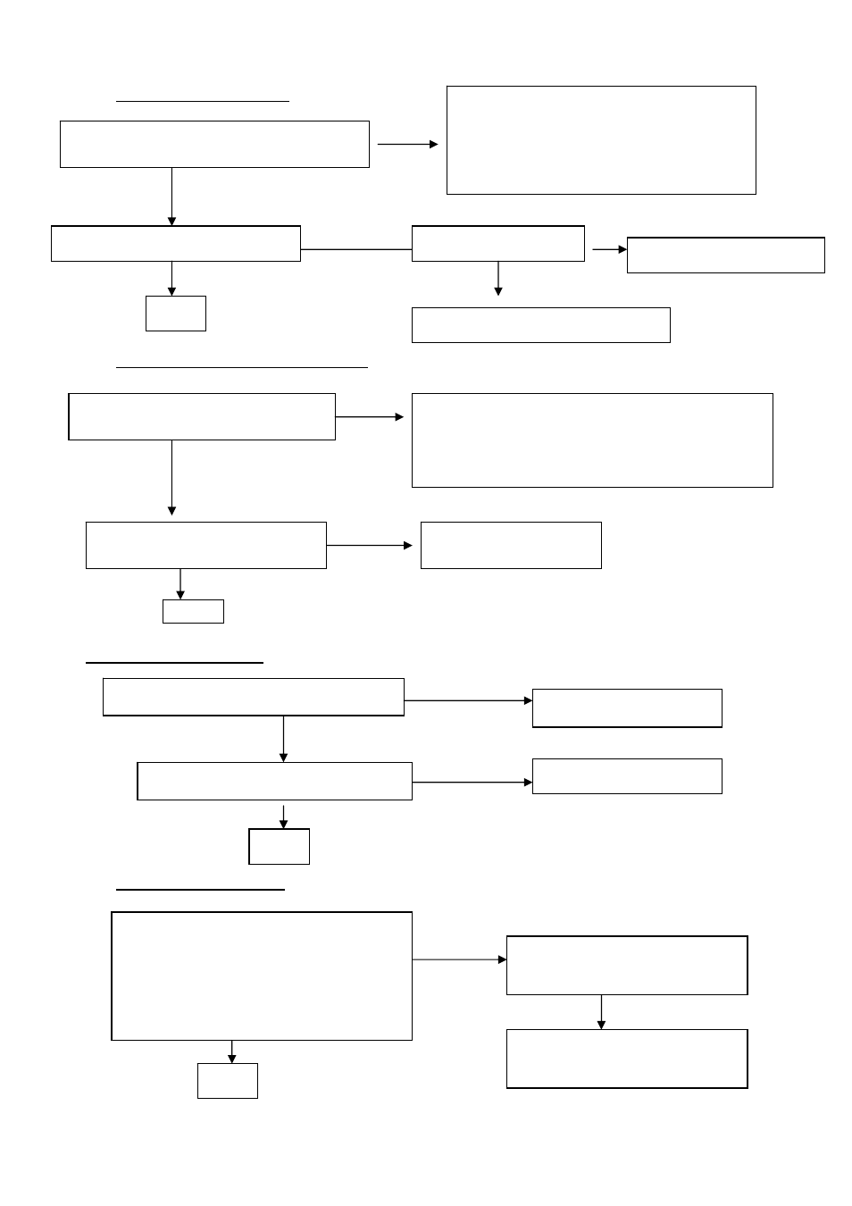
PANEL-POWER CIRCUIT
I
NVERTER Control Relative Circuit
OSCILLATOR BLOCK
U200-DATA OUTPUT
OK,R225 have response
check R225 should have response from 12V to 0V
When we switch the power switch from on to off
Check the PPWR panel power relative circuit,
R223, Q200,U202(pin 5,6,7,8)
In normal operation, when LED =green, R223
should =0 v,
If PPWR no-response when the power switch
Turn on and turn off, replace the U200-GMZAN1
NG
Measured the U202 pin 5,6,7,8= 5 V?
Replace U202 ( Nmos, SI9933)
NG, no Voltage
OK
Replace INVERTER-module
& Re-do white balance
Replace INVERTER to new-one, and
Check the screen is normal ??
Measured the inveter connector CN303
Pin 1=12V, pin 3 on/off control=5V (on)
NG, still no screen
Check the Bklt-On relative circuit, R315, Q304, R311,
In normal operation, when LED =green,
R315 Bklt-On should =0 v,
If Bklt-On no-response when the power switch turn on-off,
Replace the MCU
NG
NG
OK
OK
Measured U201 Oscillator output R215= 50mhZ ?
Replace Oscillator U201
NG,no transition
OK, has transition
Measured X300 Crystal output R340= 20mhZ ?
Replace Crystal X300
NG,no transition
OK
Measured PCLK(L207)
PVS,PHS (pin 73,74 from U200 )
Is there have any transition?
Pclk around 47MHz to 57MHZ ,
PVS=60.09Hz , PHS around 67 KHz ??(refer to
input signal=640x480@60 Hz 31k, and LED is
green)
Replace GMZAN1 (U200) or replace
MAINBOARD.
NG , no transition
OK
If MainBoard being replace , please
do the DDC – content reprogrammed
Check U202 pin 1,2,3,4= 5V
Check U304 relative circuit.(R905,T300..)
NG