Front operators panel, Front, Operator's – Lenovo Secure Managed Client User Manual
Page 32: Panel
Table
6.
Power
supply
unit
LED
states
Condition
LED
state
No
AC
power
to
all
PSUs
Off
Power
supply
direct
current
(DC)
outputs
ON
and
OK
Green
No
AC
power
to
this
PSU
only
Amber
AC
present
/
only
standby
outputs
Blink
Green
Power
supply
failure
(includes
over
voltage,
over
temperature)
Amber
Voltage
regulator
module
(VRM)
failure
(cage
related)
Blink
green
240VA
limit
(cage
related)
Blink
green
Current
limit
Amber
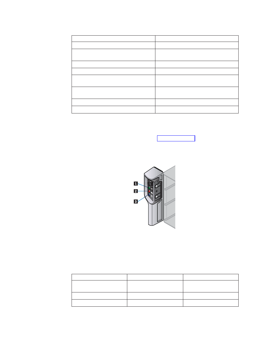
Front
operator's
panel
The
front
operator’s
panel
displays
the
aggregated
status
of
all
the
modules.
Front
operator’s
panel
LED
states
are
defined
in
Note:
The
front
operator’s
panel
is
supplied
as
an
integral
part
of
the
enclosure
core
product
and
is
not
user
replaceable.
1 Power
active
LED
2 Unit
fault
LED
3 Enclosure
ID
LED
Table
7.
Ops
panel
LED
states
LEDs
Normal
Operation
Fault
condition
Power
active
Constant
green:
good
or
positive
indication
Unit
fault
Off
Constant
amber:
fault
present
Enclosure
ID
Blue:
only
when
activated
Blue:
only
when
activated
Figure
21.
Front
operator’s
panel
LEDs
24
User
Guide