Lenovo V580c Notebook User Manual
Page 76
For access, remove these FRUs in order:
•
“1010 Battery pack” on page 46
•
“1020 Bottom slot cover” on page 46
•
“1030 Optical drive or blank bezel” on page 47
•
“1040 Memory modules” on page 49
•
“1050 Hard disk drive assembly” on page 50
•
“1060 PCI Express Mini Card for wireless LAN” on page 52
•
“1070 mSATA solid-state drive” on page 54
•
“1080 Backup battery” on page 55
•
•
“1100 Keyboard bezel” on page 58
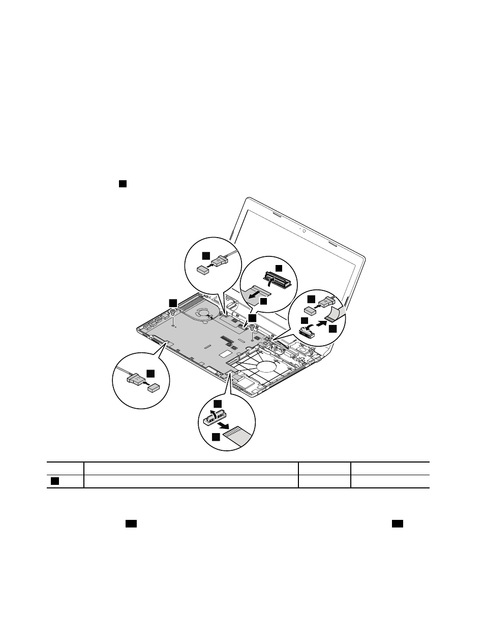
Removal steps of system board assembly
Remove the screws
1
, and then detach the connectors as shown in the following illustration.
9
8
10
2
5
7
6
3
4
1
1
Step
Screw (quantity)
Color
Torque
1
M2 × 5 mm, flat-head, nylon-coated (3)
Silver
1.85 kgf-cm
When installing: Ensure that all the connectors are attached firmly.
Detach the connector
11
, and then remove the system board in the direction shown by the arrow
12
.
70
Hardware Maintenance Manual