Connecting ide and floppy cables, Support four usb connectors – AOpen D X37PU-EG-E0110A User Manual
Page 4
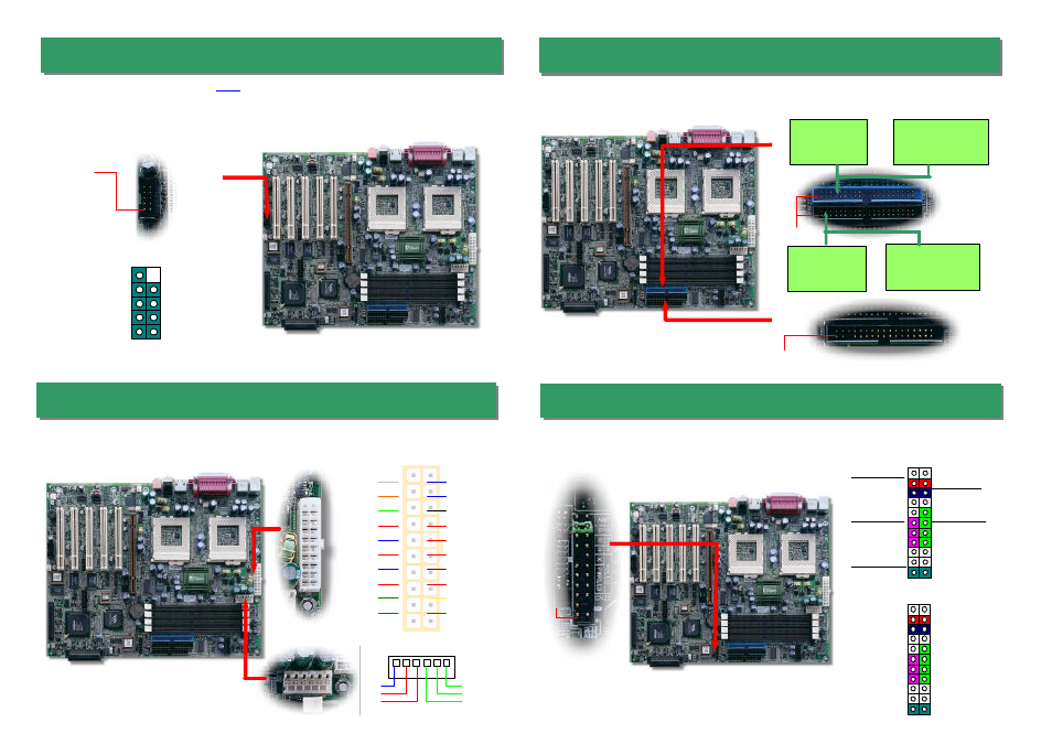
Pin 1
Secondary
Master (3rd)
Secondary
Slave (4th)
Primary
Slave (2nd)
Primary
Master (1st)
8. Connecting IDE and Floppy Cables
9. Connecting Front Panel Cable
7. Connecting ATX and AGP Pro Power Connector
Connect 34-pin floppy cable and 40-pin, 80-wire IDE cable to floppy connector FDC and
IDE connector. Be careful of the pin1 orientation. Wrong orientation may cause system
damage.
Pin 1
ATA 33/66/100
IDE Connector
FDD Connector
IDE 1 (Primary)
IDE 2 (Secondary)
6. Support Four USB Connectors
This motherboard provides four
USB
connectors to connect USB devices, such as
mouse, keyboard, modem, printer, etc. There are two connectors on the PC99 back
panel. You can use proper cable to connect other USB connectors to the back panel or
front panel of chassis.
Pin 1
1
KEY
GND
SBD2+
SBD2-
+5V
NC
GND
SBD3+
SBD3-
+5V
USB2 Connector
Pin 1
The DX37Plus -U uses standard ATX power connector. The 6-pin AGP Pro Power
connector provides extra +5V and +3.3V power for AGP Pro VGA card. Make sure you
plug in the right direction.
+5V
COM
-5V
COM
+5V
+3.3V
+3.3V
COM
COM
COM
PS-ON
-12V
COM
+3.3V
5VSB
+5V
COM
+12V
PW-OK
+5V
+3.3V
+3.3V
GND
GND
GND
1
6
Attaching such as power LED, speaker, reset switch, power switch connector, etc.… to
corresponding pins. The green cap on pin 19 & 20 is to disable Chassis Intrusion
Switch, you may just take it off to able this function.
1 2
Reset Switch
HDD LED
ATX Power
Switch
Power LED
Chassis Intrusion
Switch
21 22
GND
GND
+5V
HDD LED
HDD LED
+5V
GND
INT S/W
RST S/W
+5V
GND
PWR LED
+5VSB
21 22
1 2