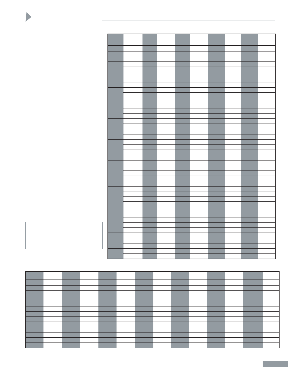
Dimensions, Hh-8, Front flange dimensions – Sheffer HH SERIES User Manual
Page 9
Good – Front Flange Mount
While this style of mount is a widely
used one, its use should be restricted
to pressures under 1000 psi, short
strokes (under 36") and standard rod
diameters. Note that the Front Head
Flange mount has the same mounting
hole pattern.
Better – Front Flange
Extra Mount
Satisfactory for maximum operating
pressure and long strokes if properly
applied. See separate Accessories
Brochure for detailed mounting data
and separate Engineering Brochure for
long stroke information.
Best – Front Head Flange
Mount
Highly recommended. This is the best
style of flange mounting. With this
style, the cylinder can be mounted on
the back face of the Head Flange if
desired. This mounting style is used
extensively on high tonnage presses
and other heavy duty applications. To
dimensionally interchange with the FF
mount, see separate Accessories Brochure
for Front Head Flange Spacer Bars.
We highly recommend that considera-
tion be given to the use of a Style 6 rod
end (see pages HH-21 and HH-22)
and S.A.F.E. Coupling (see separate
Accessories Brochure) to achieve good
radial alignment.
Selection of piston rod diameter can be
determined by consulting the separate
Engineering Brochure.
CAUTION
See separate Accessories Brochure
for information concerning the
application of Flange Mount Cylinders.
MM
ROD
BORE
DIA.
FA
RD
VB
W
WF
WG
Y
ZB
*
1
1
/
8
5
/
8
STD.
—
—
—
5
/
8
1
1
/
8
2
1
/
4
1
23
/
32
4
5
/
8
*
5
/
8
STD.
—
—
—
5
/
8
1
2
3
/
4
2
5
15
/
16
*
1 2:1
—
—
—
1
1
3
/
8
3
1
/
8
2
3
/
8
6
5
/
16
*
1 STD.
11
/
32
2.375
7
/
8
3
/
4
1
3
/
8
3
1
/
8
2
3
/
8
6
7
/
16
*
1
3
/
8
2:1
19
/
32
2.875
1
1
1
5
/
8
3
3
/
8
2
5
/
8
6
11
/
16
*
1 STD.
11
/
32
2.375
7
/
8
3
/
4
1
3
/
8
3
1
/
8
2
3
/
8
6
9
/
16
*
1
3
/
8
19
/
32
2.875
1
1
1
5
/
8
3
3
/
8
2
5
/
8
6
13
/
16
*
1
3
/
4
2:1
—
—
—
1
1
/
4
1
7
/
8
3
5
/
8
2
7
/
8
7
1
/
16
*
1
3
/
8
STD.
19
/
32
2.875
1
7
/
8
1
5
/
8
3
5
/
8
2
3
/
4
7
11
/
16
*
1
3
/
4
19
/
32
3.250
1
1
/
8
1
1
/
8
1
7
/
8
3
7
/
8
3
7
15
/
16
*
2 2:1
—
—
—
1
1
/
4
2
4
3
1
/
8
8
1
/
16
*
1
3
/
4
STD.
19
/
32
3.250
1
1
/
8
1
1
7
/
8
3
7
/
8
3
8
3
/
16
*
2
19
/
32
3.562
1
1
/
8
1
1
/
8
2
4
3
1
/
8
8
5
/
16
*
2
1
/
2
2:1
19
/
32
4.000
1
1
/
4
1
3
/
8
2
1
/
4
4
1
/
4
3
3
/
8
8
9
/
16
*
2 STD.
19
/
32
3.562
1
1
/
8
1
1
/
8
2
4
3
1
/
8
9*
2
1
/
2
19
/
32
4.000
1
1
/
4
1
3
/
8
2
1
/
4
4
1
/
4
3
3
/
8
9
1
/
4
*
3
19
/
32
4.750
1
1
/
4
1
3
/
8
2
1
/
4
4
1
/
4
3
3
/
8
9
1
/
4
*
3
1
/
2
2:1
23
/
32
5.187
1
1
/
4
1
3
/
8
2
1
/
4
4
1
/
4
3
3
/
8
9
1
/
4
*
2
1
/
2
STD.
19
/
32
4.000
1
1
/
4
1
1
/
4
2
1
/
4
4
5
/
8
3
1
/
2
10
1
/
2
*
3
19
/
32
4.750
1
1
/
4
1
1
/
4
2
1
/
4
4
5
/
8
3
1
/
2
10
1
/
2
*
3
1
/
2
23
/
32
5.187
1
1
/
4
1
1
/
4
2
1
/
4
4
5
/
8
3
1
/
2
10
1
/
2
*
4 2:1
23
/
32
5.750
1
1
/
4
1
1
/
4
2
1
/
4
4
5
/
8
3
1
/
2
10
1
/
2
*
3 STD.
19
/
32
4.750
1
1
/
4
1
1
/
4
2
1
/
4
5
1
/
8
3
13
/
16
11
15
/
16
*
3
1
/
2
23
/
32
5.187
1
1
/
4
1
1
/
4
2
1
/
4
5
1
/
8
3
13
/
16
11
15
/
16
*
4
23
/
32
5.750
1
1
/
4
1
1
/
4
2
1
/
4
5
1
/
8
3
13
/
16
11
15
/
16
*
4
1
/
2
3
/
4
6.250
1
1
/
4
1
1
/
4
2
1
/
4
5
1
/
8
3
13
/
16
11
15
/
16
*
5 2:1
3
/
4
6.750
1
1
/
4
1
1
/
4
2
1
/
4
5
1
/
8
3
13
/
16
11
15
/
16
*
3
1
/
2
STD.
23
/
32
5.187
1
1
/
4
1
1
/
4
2
1
/
4
5
1
/
2
3
15
/
16
13*
4
23
/
32
5.750
1
1
/
4
1
1
/
4
2
1
/
4
5
1
/
2
3
15
/
16
13*
4
1
/
2
3
/
4
6.250
1
1
/
4
1
1
/
4
2
1
/
4
5
1
/
2
3
15
/
16
13*
5
3
/
4
6.750
1
1
/
4
1
1
/
4
2
1
/
4
5
1
/
2
3
15
/
16
13*
5
1
/
2
2:1
3
/
4
7.250
1
1
/
4
1
1
/
4
2
1
/
4
5
1
/
2
3
15
/
16
13*
4
1
/
2
STD.
1
5
/
8
6.250
1
15
/
16
1
1
/
4
2
15
/
16
6
13
/
16
5
16
3
/
4
*
5
1
5
/
8
6.750
2
3
/
16
1
1
/
2
3
3
/
16
7
1
/
16
5
1
/
4
17*
5
1
/
2
1
5
/
8
7.250
2
3
/
16
1
1
/
2
3
3
/
16
7
1
/
16
5
1
/
4
17*
7 2:1
1
5
/
8
9.750
2
3
/
16
2
3
11
/
16
7
9
/
16
5
3
/
4
17
1
/
2
*
5
1
/
2
STD.
1
5
/
8
7.250
2
3
/
16
1
1
/
4
3
3
/
16
8
1
/
16
5
3
/
4
19
5
/
8
*
7
1
5
/
8
9.75
2
3
/
16
1
7
/
8
3
13
/
16
8
11
/
16
6
3
/
8
20
1
/
4
*
8 2:1
1
7
/
8
10.875
2
7
/
16
2
7
/
16
4
3
/
8
9
1
/
4
6
15
/
16
20
13
/
16
*
7 STD.
2
3
/
8
9.75
2
13
/
16
1
7
/
8
4
5
/
16
9
11
/
16
7
7
/
16
23
15
/
32
*
10 2:1
2
3
/
8
13.73
2
15
/
16
2
1
/
2
4
15
/
16
10
5
/
16
8
1
/
16
24
3
/
32
*
*
Be sure to add stroke to this dimension.
EE
EE
BORE
E
NPT†
SAE
FB**
FF
G
J
K
LB*
P
*
R
TF
UF
1
1
/
8
1
3
/
4
1
/
4
-6
1
/
4
1
/
2
1
1
/
8
1
1
/
4
3
1
/
4
*
2
3
/
16
*
1.19
2
3
/
8
3
1
1
/
2
2
1
/
2
1
/
2
-10
3
/
8
3
/
8
1
3
/
4
1
1
/
2
5
/
16
4
5
/
8
*
2
7
/
8
*
1.63
3
7
/
16
4
1
/
4
2
3
1
/
2
-10
1
/
2
5
/
8
1
3
/
4
1
1
/
2
7
/
16
4
5
/
8
*
2
7
/
8
*
2.05
4
1
/
8
5
1
/
8
2
1
/
2
3
1
/
2
1
/
2
-10
1
/
2
5
/
8
1
3
/
4
1
1
/
2
7
/
16
4
3
/
4
*
3*
2.55
4
5
/
8
5
5
/
8
3
1
/
4
4
1
/
2
3
/
4
-12
5
/
8
3
/
4
2
1
3
/
4
9
/
16
5
1
/
2
*
3
1
/
2
*
3.25
5
7
/
8
7
1
/
8
4
5
3
/
4
-12
5
/
8
7
/
8
2
1
3
/
4
9
/
16
5
3
/
4
*
3
3
/
4
*
3.82
6
3
/
8
7
5
/
8
5
6
1
/
2
3
/
4
-12
7
/
8
7
/
8
2
1
3
/
4
3
/
4
6
1
/
4
*
4
1
/
4
*
4.95
8
3
/
16
9
3
/
4
6
7
1
/
2
1
-16
1
1
2
3
/
8
2
3
/
8
7
/
8
7
3
/
8
*
4
7
/
8
*
5.73
9
7
/
16
11
1
/
4
7
8
1
/
2
1
1
/
4
-20
1
1
/
8
1
2
7
/
8
2
7
/
8
1
3
/
16
8
1
/
2
*
5
3
/
8
*
6.58
10
5
/
8
12
5
/
8
8
9
1
/
2
1
1
/
2
-24
1
1
/
4
1
3
1
/
4
3
1
/
4
1
1
/
4
9
1
/
2
*
6
1
/
8
*
7.50
11
13
/
16
14
10
12
5
/
8
2
-32
1
3
/
4
1
11
/
16
3
7
/
8
3
7
/
8
1
11
/
16
12
1
/
8
*
8*
9.62
15
7
/
8
19
12
14
7
/
8
2
1
/
2
-32
2
1
15
/
16
4
7
/
8
4
7
/
8
1
15
/
16
14
1
/
2
*
9
3
/
8
*
11.45
18
1
/
2
22
14
17
1
/
4
2
1
/
2
-32
2
1
/
4
2
7
/
16
5
3
/
8
5
3
/
8
2
5
/
32
17*
10
3
/
4
*
13.34
21
1
/
8
25
1
/
4
*
Be sure to add stroke to this dimension.
**
Clearance holes for indicated bolt size.
†
Alternate port at no extra charge. SAE port is standard.
14
12
10
8
7
6
5
4
3
1
/
4
2
1
/
2
2
1
1
/
2
1
1
/
8
" THRU 14" BORES
Dimensions
Front Flange Dimensions
Front Flange Dimensions
HH-8