Dimensions, Hh-20, Large bore dimensions – Sheffer HH SERIES User Manual
Page 21: Maximum pressure ratings, Rod end dimensions, Large bore rod end
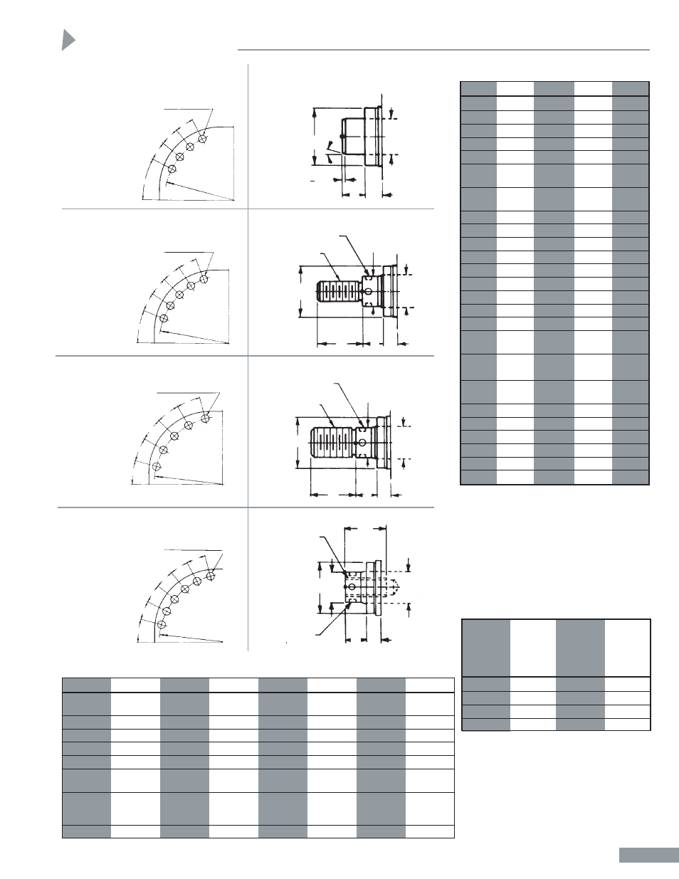
Large Bore Dimensions
BORE
16
18
20
24
CB
6
1
/
2
7
1
/
2
8
9
CD
6
7
8
9
CL
13
15
16
18
CW
3
1
/
4
3
3
/
4
4
4
1
/
2
E
23
1
/
2
27
1
/
4
31
36
1
/
2
EE
3"
3"
3"
3
1
/
2
"
MAX.
PIPE
PIPE
PIPE
PIPE
EX
DIA.
21
3
/
8
24
1
/
4
26
1
/
2
32
FA
1
1
1
1
G
5
7
/
8
6
3
/
8
7
3
/
8
7
7
/
8
J
5
7
/
8
6
3
/
8
7
3
/
8
7
7
/
8
K
3
/
4
7
/
8
7
/
8
1
1
/
16
L
7
8
9
11
LB
18
20
23
25
3
/
4
LR
6
7
8
9
MR
6
7
8
9
P
12
1
/
4
13
1
/
4
14
1
/
4
16
3
/
4
PA
MAX.
5
5
/
16
5
5
/
16
5
5
/
16
6
PB
MAX.
2
3
/
4
2
3
/
4
2
3
/
4
3
1
/
2
PC
MAX.
4
1
/
4
4
1
/
4
4
1
/
4
5
WB
3
3
/
8
3
3
/
8
3
3
/
8
4
XC
28
3
/
8
31
3
/
8
35
3
/
8
40
3
/
4
Y
6
1
/
4
6
3
/
4
7
3
/
4
8
1
/
2
ZB
22
1
/
8
24
1
/
4
27
1
/
4
30
13
/
16
ZC
34
3
/
8
38
3
/
8
43
3
/
8
49
3
/
4
ZJ
21
3
/
8
23
3
/
8
26
3
/
8
29
3
/
4
Maximum Pressure Ratings
3:1
HEAVY
MAX.
SAFETY
DUTY
SHOCK
FACTOR
BORE
SERVICE
SERVICE
(YIELD)
SIZE
PSI
PSI
PSI
16
3,000
5,000
2380
18
3,000
5,000
2417
20
3,000
5,000
2447
24
3,000
5,000
2323
Rod End Dimensions
BORE
16
16
16
18
18
20
24
MM
ROD DIA.
8
9
10
9
10
10
12
A
8
9
10
9
10
10
12
C
1
1
1
1
1
1
1
CC
7
3
/
4
-12
8
3
/
4
-12
9
3
/
4
-12
8
3
/
4
-12
9
3
/
4
-12
9
3
/
4
-12
11
3
/
4
-12
KK
5
3
/
4
-12
6
1
/
2
-12
7
1
/
4
-12
6
1
/
2
-12
7
1
/
4
-12
7
1
/
4
-12
8
3
/
4
-12
NA
±.002
7.875
8.875
9.875
8.875
9.8775
9.875
11.875
RD
–.001
–.003
10.875
12.500
13.750
12.500
13.750
13.750
16.500
VB
2
3
/
8
2
3
/
8
2
3
/
8
2
3
/
8
2
3
/
8
2
3
/
8
3
Large Bore Rod End
STYLE 2 STANDARD
Style 3
Style 4
RD
RD
RD
RD
A
A
A
C
C
C
VB
VB
VB
KK THREAD
CC THREAD
KK THREAD
1
/
2
"
SPANNER
HOLES
1
/
2
"
SPANNER
HOLES
1
/
2
"
SPANNER
HOLES
20°
MM
DIA.
MM
DIA.
MM
DIA.
MM
DIA.
NA DIA.
NA DIA.
NA
DIA.
VB
C
1
/
16
-0
1
8
23
9
/
16
B. C.
1
5
/
16
DIA.
4 HOLES
PER
CORNER
12
°
12°
27°
12
°
1
5
/
16
DIA.
5 HOLES
PER
CORNER
18" BORE
1
2
°
12
°
12°
26
1
/
2
B. C.
20" BORE
15
°
15°
15°
29
B. C.
1
5
/
16
DIA.
6 HOLES PER
CORNER
24" BORE
1
2
°
1
2
°
12
°
Details of Placement of
Mounting Holes in Each Corner
IMPORTANT NOTE:
All figures in the chart below are
based on the cylinders as a pressure
vessel. Some styles of mounting will
not withstand the thrust generated at
these pressures. Contact the factory
for specific data.
21°
12°
15°
15°
15°
12°
12°
1
9
/
16
DIA.
5 HOLES PER
CORNER
34
B. C.
16" THRU 24" BORES
Dimensions
16" BORE
Style 1
1
HH-20