Fan power connector: cpufan1, sysfan1, auxfan1, Serial port connector: com2, Important – MSI 945GC Networks User Manual
Page 27
2-11
Hardware Setup
Fan Power Connector: CPUFAN1, SYSFAN1, AUXFAN1
The fan power connectors support system cooling fan with +12V. W hen connecting
the wire to the connectors, always note that the red wire is the positive and should
be connected to the +12V; the black wire is Ground and should be connected to GND.
If the mainboard has a System Hardware Monitor chipset onboard, you must use a
specially designed fan with speed sensor to take advantage of the CPU fan control.
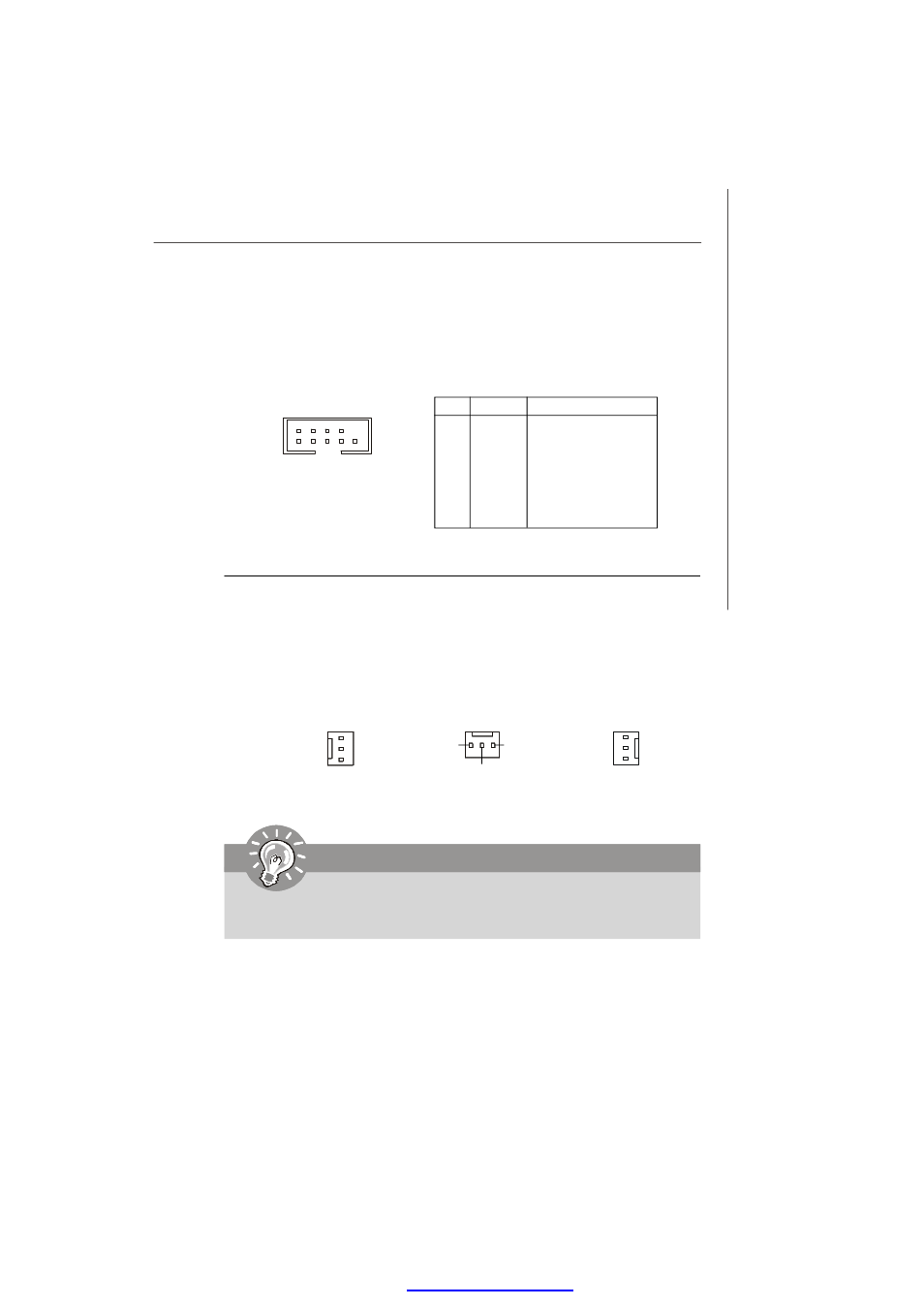
Serial Port Connector: COM2
This connector is a 16550A high speed communications port that sends/receives 16
bytes FIFOs. You can attach a serial device to it through the optional serial port
bracket.
PIN
SIGNAL
DESCRIPTION
1
DCD
Data Carry Detect
2
SIN
Serial In or Receive Data
3
SOUT
Serial Out or Transmit Data
4
DTR
Data Terminal Ready
5
GND
Ground
6
DSR
Data Set Ready
7
RTS
Request To Send
8
CTS
Clear To Send
9
VCC_COM
Power Source
Pin Definition
AUXFAN1
SE NS OR
+1 2V
GND
SYSFAN1
SE NS OR
+1 2V
GND
COM2
1
9
2
10
Important
Please refer to the recommended CPU fans at CPU vendor
’s official website
or consult the vendors for proper CPU cooling fan.
CPUFAN1
SE NS OR
+1 2V
GND
PDF created with pdfFactory Pro trial versi