Programming guide – MSI 945GC Networks User Manual
Page 23
2-7
Hardware Setup
Programming Guide
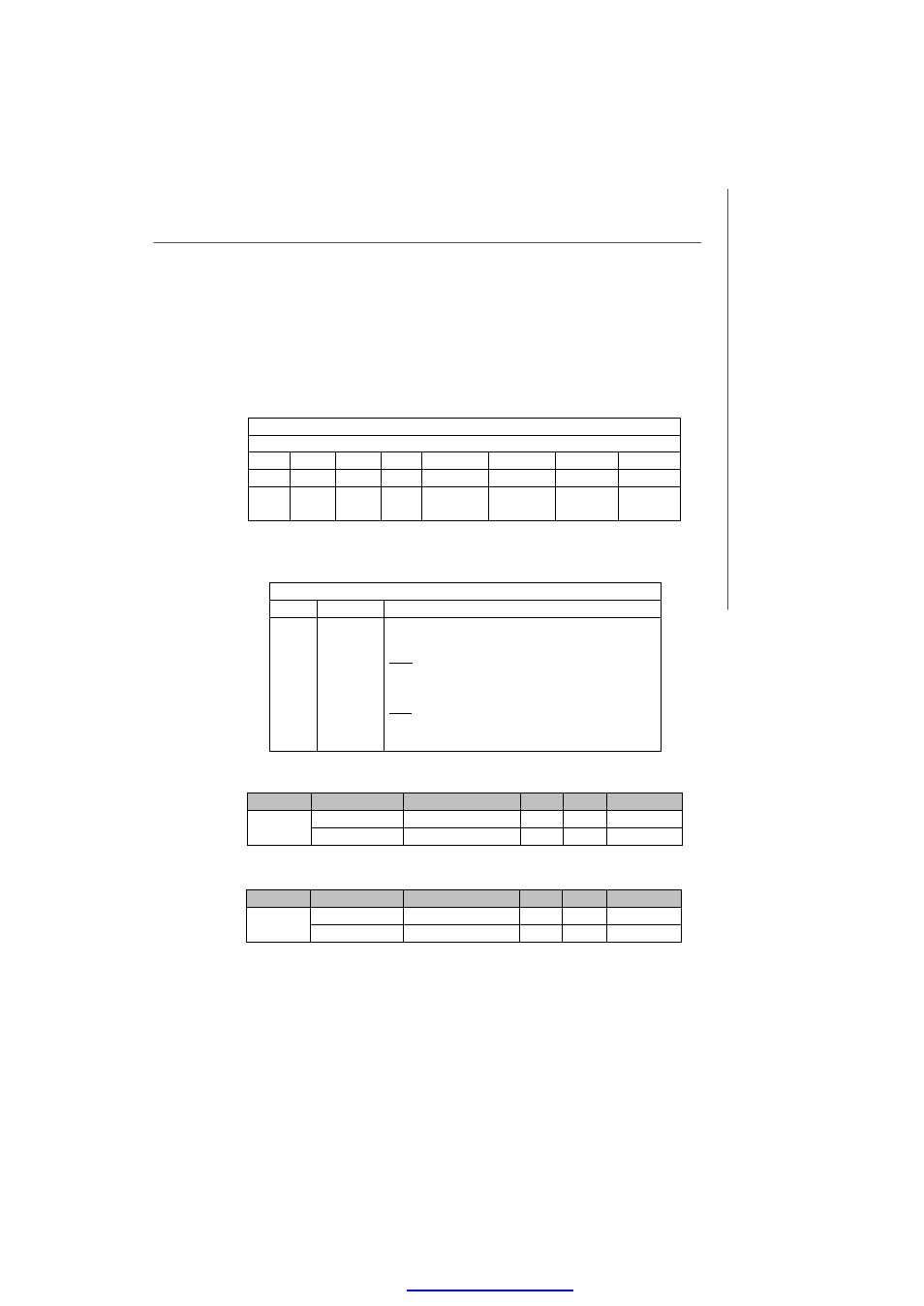
LPC I/O address: 5E
Power ON/OFF State Bypass Control Status Register
Set/Read bypass mode
Default Value: 0xD0 (Base on Customer Demand)
Power ON/OFF State Bypass Control Status Register
I/O Address: 5E
7
6
5
4
3
2
1
0
X
X
X
X
R/W
R/W
R/W
R/W
Not
Used
Not
Used
Not
Used
Not
Used
Segment 4
Segment 3
Segment 2
Segment 1
Bit Definition
Power ON/OFF State Bypass Control Status Register
Bit Field
Name
Value
3:0
Segment
1 to 4
Segment control bit. Each bit corresponds to a specific segment
numbered 1 thru 4.
Write:
1: Force Bypass
0: Force Pass Through
Read:
1: Bypass Mode
0: Pass Through Mode
PWRON Signal Action
Segment
Signal Name
Description
Type
Bypass
Pass Through
RELAY_SET2#
Enable LAN 1~2 bypass
Output
1
0
Segment 2
RESET_RESET2#
Enable LAN 1~2 bypass
Output
0
1
PWROFF Signal Action
Segment
Signal Name
Description
Type
Bypass
Pass Through
RELAY_SET2#
Enable LAN 1~2 bypass
Output
1
0
Segment 4
RESET_RESET2#
Enable LAN 1~2 bypass
Output
0
1
PDF created with pdfFactory Pro trial versi