Warning, Danger, Maintenance (continued) – Howard SVR1 Regulator User Manual
Page 14
Document 2.4.114
SVR-1 Step Voltage Regulator
Copyright © 2012 Howard Industries, Inc.
Document No. 2.4.114
Revision: 03
Issued: March, 2012
14
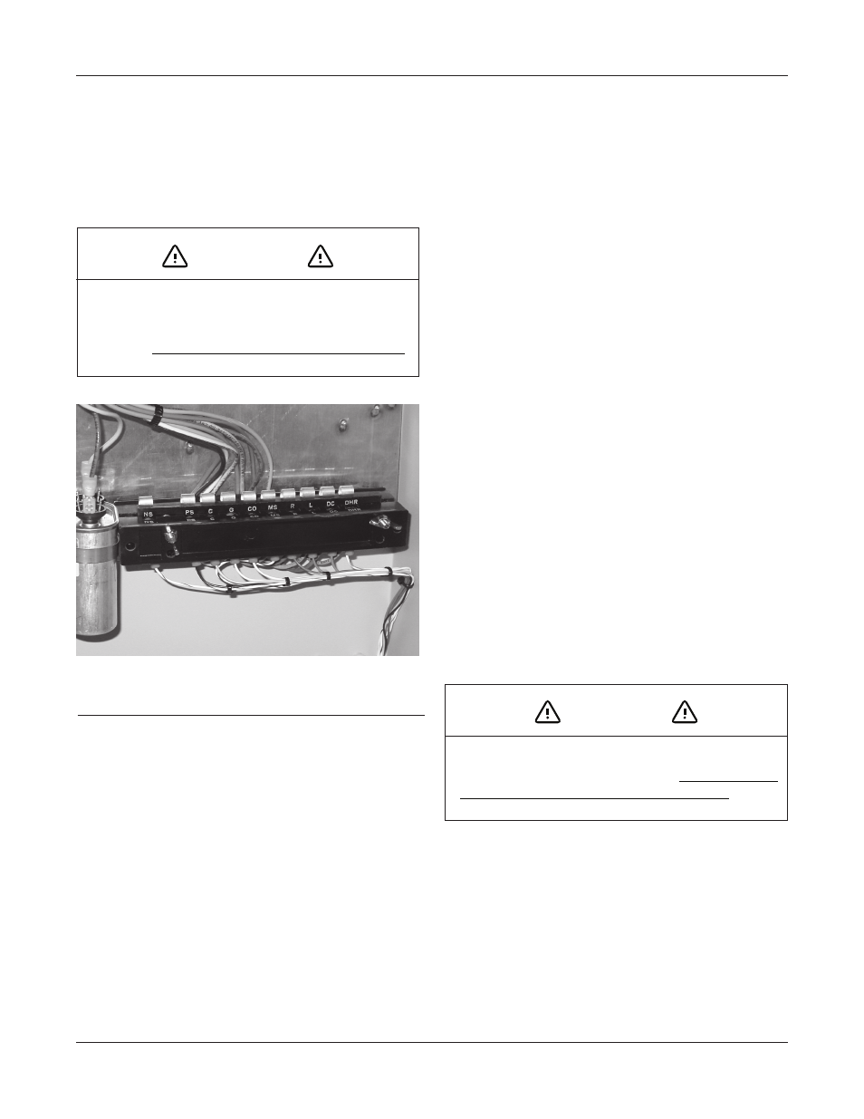
The control panel is hinged and may be removed
completely from the regulator control enclosure. It is
not necessary to bypass or de-energize the regulator to
remove the control panel. To remove the control panel,
remove the two wing nuts on the Connector Terminal Strip
(CTS) and disconnect the CTS (Figure 10). The spring-
loaded shorting contacts in the CTS will automatically
maintain the necessary electrical connections to allow
removal and replacement of the control panel without
de-energizing it.
CTS terminal designations are as follows:
“PS” – Panel source
“MS” – Motor source
“G” – Ground
“CO” – Current transformer negative (–)
“C”
– Current transformer positive (+)
“DHR” – Drag hand reset
“L”
– Lower
“R” – Raise
“NS” – Neutral switch
“OC” – Operations counter
INSUlATING FlUID
Determine the condition of the insulating fluid using the
following procedure:
1. Withdraw a sample of the insulating fluid using the
sampling device located in the drain valve at the
bottom of the tank.
2. Measure the dielectric strength of the oil per
ASTM D-877. If found to be below 24 kV, the oil
should be filtered and retested. Other tests such as
“neutralization number,” “interfacial tension,” and
“power factor” are also useful and may be desired by
some users.
3. Add oxidation inhibitor (2,6-ditertiary-butyl-
para-cresol, DBPC) to the insulation fluid at a
concentration of 0.2 to 0.3 percent, to replace
inhibitor that is naturally depleted over a period of a
few years.
INTERNAl INSPECTION
Internal inspection, while not absolutely necessary, will
help identify problems that could cause future service
interruptions.
1. Untank the regulator using the following procedure:
•
Remove the regulator from service as described
on page 12.
•
Move the regulator if necessary to provide
adequate working room and the necessary vertical
clearance to lift the internal assembly out of the
tank. Be careful to avoid overhead lines.
•
Operate pressure relief valve to vent regulator
If the regulator is not operating properly, the first step in
troubleshooting should be the replacement of the control
unit with one known to be in good operating condition.
MAINTENANCE (Continued)
WARNING
Dangerous voltage is present at the Connector
Terminal Strip and the motor capacitor terminals.
Contact with these voltages inside the control
enclosure can cause death or serious personal injury.
FIGURE 10
: Connector Terminal Strip (CTS) located in
control enclosure.
DANGER
Exercise extreme caution when moving the regulator.
Contact with energized overhead lines will cause death,
serious personal injury, and property damage.