Caution, Placing a regulator in service – Howard SVR1 Regulator User Manual
Page 10
Document 2.4.114
SVR-1 Step Voltage Regulator
Copyright © 2012 Howard Industries, Inc.
Document No. 2.4.114
Revision: 03
Issued: March, 2012
10
PlACING A REGUlATOR IN SERVICE
PROCEDURE FOR PlACING IN SERVICE
After completing the installation procedure outlined in the
previous section, the regulator can be placed into service
using the following procedure.
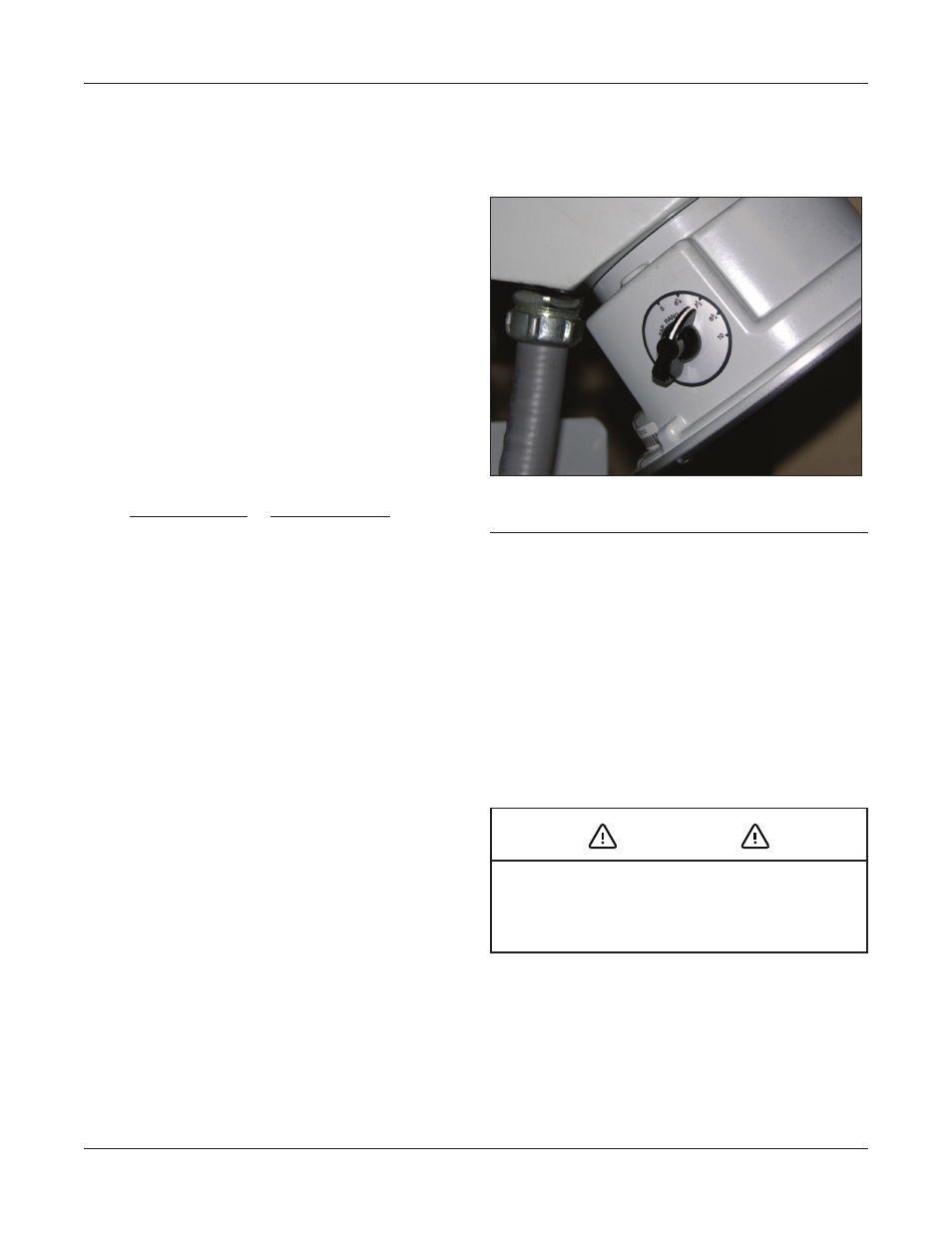
1. Set HI-AMP™ limits, if necessary, using the rotary
switches located on either side of the position
indicator (Figure 9).
The HI-AMP™ feature allows the
SVR-1 regulator to be operated above rated load by
decreasing the range of operation in 1.25 percent
increments. Load current may be increased up to
160 percent of rated current (maximum of 668
Amps) when the regulator is operated at ± 5 percent
regulation. Percentages of current ratings for various
regulation ranges are as follows:
All that is necessary to adjust the range of regulation
anywhere from ±5 percent to ±10 percent is to
set the Hi-AMP™ switches to the desired range of
regulation is shown. The upper and lower limits
need not be the same. (Upper and lower limits of
operation can also be implemented with the digital
control unit.)
It is not necessary to remove the regulator from
service to make this adjustment; however, switches
should not be set while the motor is running.
2. Program the control unit as desired. Refer to the
manual supplied with the control unit.
3. Make absolutely certain that the regulator is in
neutral (0) position. Refer to both the position
indicator pointer and the neutral indicator on
the control panel. The position indicator must
point to “zero,” and the neutral indicator must be
continuously illuminated (The control panel can be
powered from a 120 Volt external source.)
4. Turn MAIN POWER and MOTOR CONTROL switches
to “OFF.”
5. Remove motor fuse.
6. Close the SL disconnect switch (Delta connections
only).
7. Sequentially close the source and then the load
disconnect switches.
8. Open the bypass switch.
9. Visually observe that bypass circuit is open.
10. Replace motor fuse.
11. Switch MAIN POWER switch to “INTERNAL.”
Voltage Range (%)
Current Rating (%)
±10
100
±8.75
110
±7.5
120
135
±5
160
±6.25
FIGURE 9
: One of two HI-AMP™ switches located on each
side of control position indicator
CAUTION
Operation of the regulator to extreme tap positions
can produce a line voltage that is above or below the
desired operating limit of the load.