Changes to the emi filter, An359 – Cirrus Logic AN359 User Manual
Page 3
AN359
AN359REV1
3
5. Changes to the EMI Filter
The following changes were implemented to create an EMI filter optimized for operation with the CS1501:
- The input capacitor for the PFC is too small. Capacitor C
IN
was increased to 0.47µF. This resulted in a clean
voltage at V
DC_IN
, eliminating the jitter on the PFC switching.
- Capacitor C5 was reduced to 0.47µF.
- The locations of DM choke, L1, and CM choke, L2, were swapped, resulting in two poles at lower
frequencies, formed by L1/C5 and L2/C4. The common mode (CM) choke L2 had a small differential
inductance, especially compared to L1, which is normal for CM chokes. The resultant pole created by L2 and
C4 is high-frequency, and ineffective in dealing with differential noise. CM choke L2 still formed a differential
filter with C3, and a common mode filter with the Y-capacitors C1 and C2. Its operation was not affected by
moving it to this location.
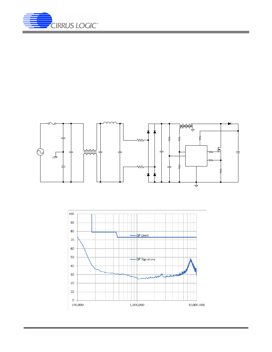
Figure 3 illustrates a typical CS1501 PFC circuit with the changes to the EMI filter mentioned above.
Figure 3. Typical EMI Filter for a CS1501 PFC Controller
After the changes to the filter were made, the EMI signature was measured and plotted in Figure 4.
Figure 4. EMI Measurement After EMI Filter Changes
C
IN
+
Q
B
CS1501
PFC
CONTROLLER
L
B
R
NTC
R
NTC
CM
Choke
DM
Choke
Y-CAP
Y-CAP
FUSE
C1
C2
C3
L1
C4
L2
C5
C
F
AC
X-CAP
X-CAP
X-CAP
V
DC_IN