Test results, An359 – Cirrus Logic AN359 User Manual
Page 2
AN359
2
AN359REV1
Table 1 lists the circuit components that influence the EMI filter’s impedance profile.
Table 1. EMI Filter Components
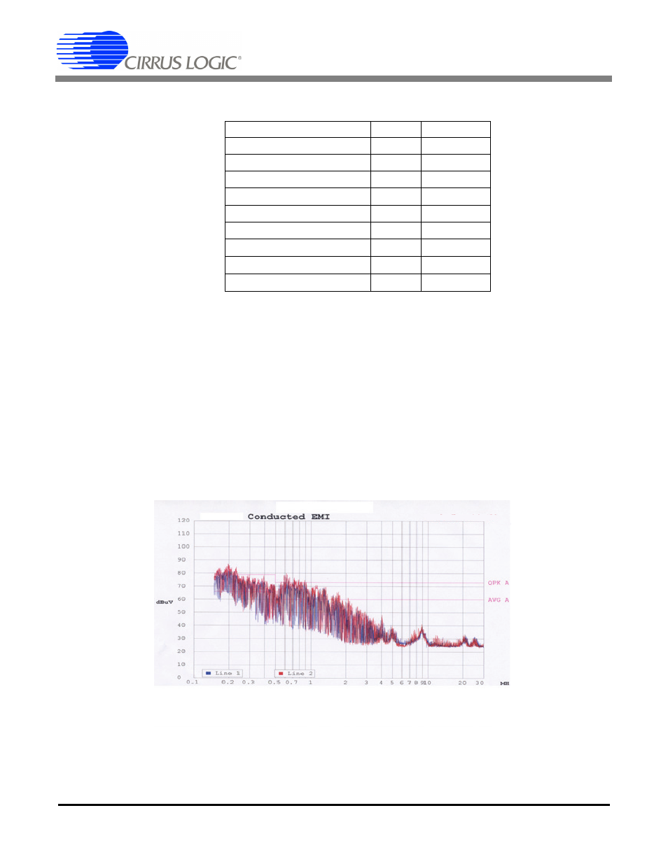
4. Test Results
Initial testing of the circuit demonstrated an increase in the measured EMI when the ST Microelectronics L6562 was
replaced with the Cirrus Logic CS1501. This increased EMI response indicates that the filter has not been designed
to match the CS1501. The use of two NTC resistors, to reduce inrush current, and the bridge rectifier increase the
impedance at the V
DC_IN
node. The L6562 controller operates in critical conduction mode (CRM). The digital
CS1501 operates mainly in discontinuous conduction mode (DCM), which requires a lower inductance for the boost
inductor L
B
. This lower inductance leads to higher switching currents,
, being pulled through the
bridge and R
NTC
resistors. This increases the switching noise at V
DC_IN
.
The CS1501 senses the rectified AC voltage (V
DC_IN
) as part of its control loop. The bandwidth required for this elim-
inates the filtering use of the capacitor C
F
. The noise on V
DC_IN
and on the sense voltage into the controller results
in erratic switching (jitter) on the boost FET Q
B
, increasing the EMI energy of the PFC.
Figure 2. EMI Measurement Before EMI Filter Changes
Description
Qty.
Designator
Capacitor 4700pF
2
C1, C2
Capacitor 0.1µF
1
C3
Inductor 1mH
1
L1
Capacitor 0.1µF
1
C4
10 mH
1
L2
Capacitor 1µF
1
C5
Resistor 5
1
R
NTC
Capacitor 4700pF
1
C
IN
Capacitor 10nF
1
C
F
dl
V dt
L
B
=