Cirrus Logic AN258 User Manual
Introduction, Workaround, Figure 1. proposed reset circuit 1
1
Copyright
© Cirrus Logic, Inc. 2004
(All Rights Reserved)
http://www.cirrus.com
AN258
EP93xx Power-up and Reset Lockup Workaround
1. Introduction
Under certain circumstances, the EP93xx may enter into a “locked” condition on power up, when a soft-
ware reset is issued, or when an internal watchdog reset is issued. This application note provides a low-
cost workaround which will provide reliable power up and reset operation by adding a few readily-avail-
able components. A fix of this issue is planned in a future revision of the silicon.
When new silicon becomes available, applications that employ this workaround should not have to be re-
designed. Customers could use the same board design and simply not populate the additional compo-
nents except a single zero-ohm resistor.
2. Workaround
The workaround circuits take advantage of the one thing that locked conditions have in common: the red
LED stays illuminated. The basic idea of the circuits is to detect the red LED staying on for a period of
time and then to issue a manual reset to the voltage monitor IC that drives POR after an appropriate
amount of time has elapsed.
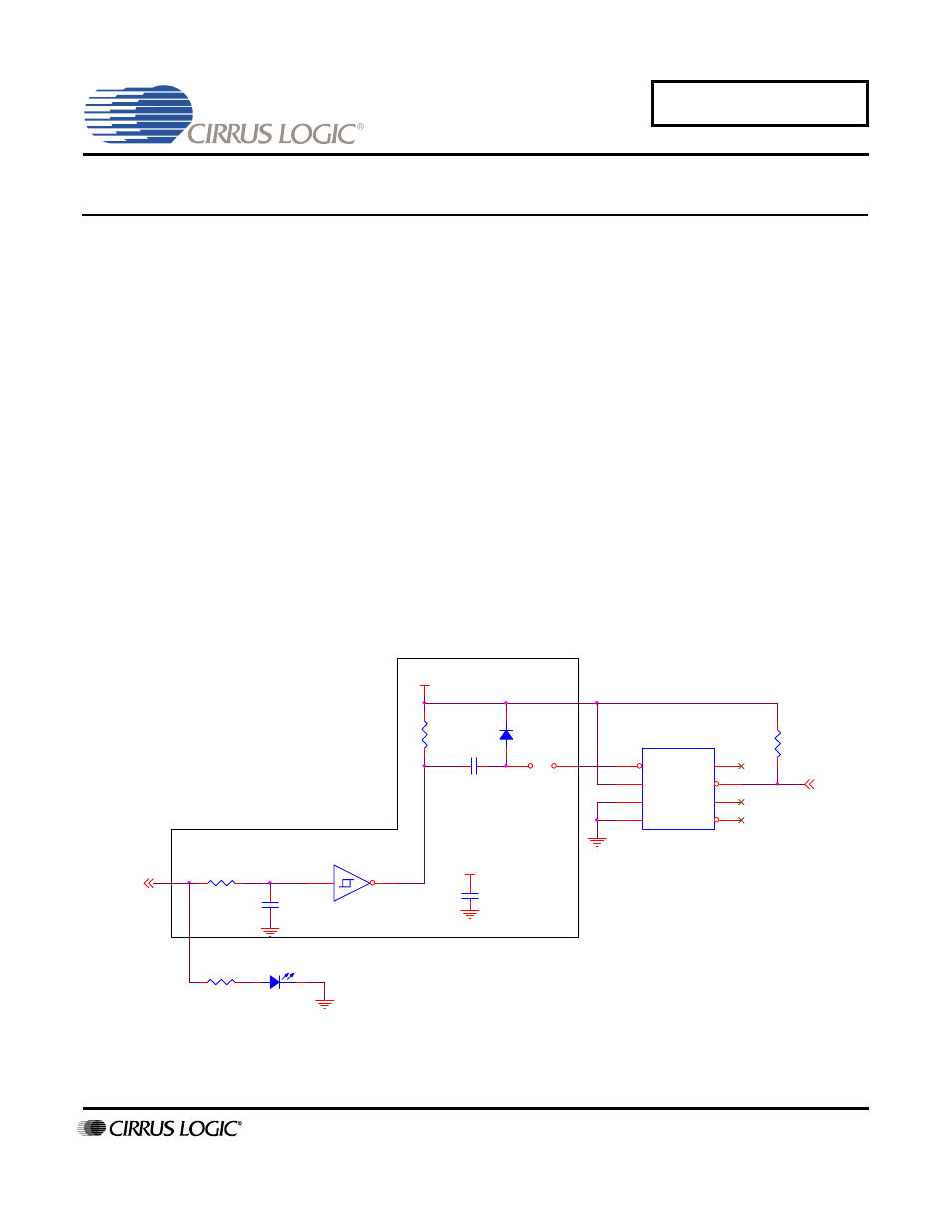
These hardware workarounds will detect this locked condition and restart the EP93xx device. It requires
a few passive devices and either a Schmitt-trigger inverter or a good-quality 2-input NAND with Schmitt
trigger. A simplified schematic of each of the proposed circuits is shown in Figure 1 and Figure 2.
Figure 1. Proposed Reset Circuit 1
RDLED
J1
JUMPER
1
2
LED1
RED_LED
U2A
74HC14/SO
1
2
C2
2.2uF
D1
R389
10K
C3
0.1uF
R1
100K
R5
560
/POR
R2
R
(DEFAULT=INSTALL)
5V
U6
MAX708CSA
1
2
3
4
5
6
7
8
/MR
Vcc
GND
PFI
/PFO
NC
/RST
RST
5V
C1
0.1uF
Oct ‘04
AN258REV2