Table 6. effect of shorting the listed pin pairs, Table 7. tx_clk mode select, Led indicators – Cirrus Logic CS8952 User Manual
Page 4: Cdb8952
4
DS206DB2
CDB8952
Crystal LAN™ 10Base-T and 100Base-X Transceiver
CIRRUS LOGIC ADVANCED PRODUCT DATABOOK
NOTE: When TX_CLK is an input, a shorting cap must
installed on HDR42 to supply TX_CLK to the
CS8952 (see HDR42).
LED Indicators
LED1 - Transmitter Active Indicator.
LED2 - Receiver Active Indicator.
LED3 - Link OK Indicator.
LED4 - Full Duplex Indicator.
LED5 - Collision Indicator.
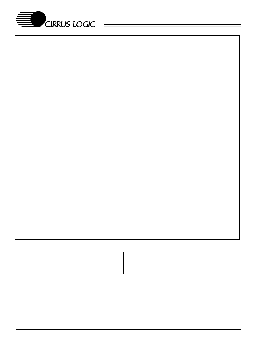
Pins
Function
Description
1-2
Low Power Start
The CS8952 will enter a low power mode following reset. Only the circuitry
necessary to maintain media impedance and the MII Serial Management
Interface will be operational. The CS8952 checks the status of these pins only
during power-on or reset. A reset or power cycle is required before any changes
in this jumper setting will take effect.
3-4
MII Receive Enable
MII signals RXD[3:0], RX_CLK, RX_DV, and RX_ER are tristated.
5-6
Power Down
The CS8952 is forced into a low power mode. Only the circuitry necessary to
maintain media impedance will be operational.
7-8
CRS Mode Control
The CRS pin will be asserted for receive activity only. The CS8952 checks the
status of these pins only during power-on or reset. A reset or power cycle is
required before any changes in this jumper setting will take effect.
9-10
Bypass Scrambler
The scrambler and descrambler are bypassed, and NRZI FX mode is enabled.
The CS8952 checks the status of these pins only during power-on or reset. A
reset or power cycle is required before any changes in this jumper setting will
take effect.
11-12 Bypass 4B/5B Coders
The 4B5B encoder and decoder are bypassed and 5-bit code groups are used.
RX_ER is used as the fifth receive bit, and TX_ER as the fifth transmit bit. The
CS8952 checks the status of these pins only during power-on or reset. A reset or
power cycle is required before any changes in this jumper setting will take effect.
13-14 Bypass Symbol
Alignment
4B5B coders, scramblers, and NRZI coders are all bypassed, and the CS8952
will make no attempt to identify code-group boundaries. Data on RXD[4:0] and
TXD[4:0] may contain bits from two code groups. The CS8952 checks the status
of these pins only during power-on or reset. A reset or power cycle is required
before any changes in this jumper setting will take effect.
15-16 Loopback
The CS8952 will be placed in loopback mode. When operating in 100 Mb/s
mode, the loopback will be inside the PMD block, and scrambled NRZI data will
be routed directly to the NRZI input port on the descrambler. When in 10 Mb/s
mode, the CS8952 will perform a local ENDEC loopback.
17-18 MII Isolate
The CS8952 will exit from reset with all MII signals tristated except MDIO and
MDC. The CS8952 checks the status of these pins only during power-on or reset.
A reset or power cycle is required before any changes in this jumper setting will
take effect.
19-20 10BASE-T Serial Mode If the CS8952 is in 10 Mb/s mode, data is transferred serially on RXD0 and
TXD0, and the full MII interface is disabled. When the CS8952 is in 100Mb/s
mode, shorting these pins has no effect. The CS8952 checks the status of these
pins only during power-on or reset. A reset or power cycle is required before any
changes in this jumper setting will take effect.
Table 6. Effect of shorting the listed pin pairs
HDR43
TX_CLK pin
CLK25 pin
pins 1-2 shorted
input
25 MHz clock
open
input
not used
pins 2-3 shorted
output
not used
Table 7. TX_CLK Mode Select