Cdb8427 – Cirrus Logic CDB8427 User Manual
Page 5
CDB8427
5
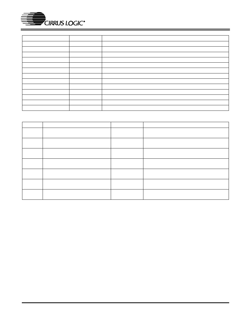
CONNECTOR
INPUT/OUTPUT
SIGNAL PRESENT
+5V
Input
+5 Volt power
GND
Input
Ground connection from power supply
OPTICAL INPUT
Input
Digital Audio Interface optical input
S/PDIF INPUT
Input
Digital Audio Interface coaxial input
AES3 INPUT
Input
Digital Audio Interface XLR input
RS232
Input/Output
Parallel RS232 port for connection to serial port of PC
OPTICAL OUTPUT
Output
Digital Audio Interface optical output (always enabled)
S/PDIF OUTPUT
Output
Digital Audio Interface coaxial output
AES3 OUTPUT
Output
Digital Audio Interface XLR output
J5
Input/Output
I/O for RMCLK, ISCLK,ILRCK, and SDIN
J6
Input/Output
I/O for OLRCK, OSCLK, OMCK, and SDOUT
J9
Input
10-pin header for external programming of Atmel AVR
µC
J10
Input/Output
12-pin header for CS8427 control from external
µC
Table 1. System Connections
JUMPER
PURPOSE
POSITION
FUNCTION SELECTED
J11
Selects physical format of digital
audio interface input
AES3 & S/PDIF
OPTICAL
Connects input as either AES3 or S/PDIF
Connects input as OPTICAL
J12
Configures AES3 INPUT
ENABLE
DISABLE
AES3 INPUT enabled
AES3 INPUT disabled
J13
Configures S/PDIF INPUT
ENABLE
DISABLE
S/PDIF INPUT enabled
S/PDIF INPUT disabled
J14
Configures OPTICAL INPUT
ENABLE
DISABLE
OPTICAL INPUT enabled
OPTICAL INPUT disabled
J16
Selects physical format of digital
audio interface output
AES3
S/PDIF
Connects output as AES3 XLR
Connects output as S/PDIF coaxial
J17
Configures S/PDFIF OUTPUT
ENABLE
DISABLE
S/PDIF OUTPUT enabled
S/PDIF OUTPUT disabled
J15
Configures HARDWARE MODE
MUTE
ENABLE
DISABLE
Enables MUTE when in hardware mode 1
Disables MUTE when in hardware mode 1
Table 2. CDB8427 Jumper Settings