Figure 11. acoustic coupling measurement method, An168 – Cirrus Logic AN168 User Manual
Page 16
AN168
16
AN168REV2
The loop gain measurement procedure is as
follows:
1) Configure the CS6422 with its default configu-
ration, with the exception of the following:
a) Mic = ‘1’ or ‘0’, depending on whether the
internal mic preamp is used or not
b) TSD = RSD = HDD = ‘1’, transmit and re-
ceive suppressors and half-duplex mode are
disabled
c) ACC = NCC = 'cleared', echo cancelers are
forced to a cleared state to prevent updates
d) AECD = NECD = ‘1’, echo cancelers are
disabled
e) TVol = +12 dB
f) NSdt = -12 dB
g) RVol = 0 dB
2) Adjust RVol until the system is just on the
verge of howling. At this point the loop gain is
0 dB, and the loss between AO and APO (out-
side the CS6422) is equal to the RVol value.
The register settings to accomplish the above are as
follows:
reg 0: 4xa0 (or cxa0 if internal mic preamp is
used); “x” is the value of RVol
reg 1: 26a2
reg 2: 0004 (default)
reg 3: 0006 (default)
reg 4: 0008 (default)
reg 5: 033a
RVol contains a 4-bit value that results in a gain
given by the following equation:
For example, if the RVol value required to make
the system howl is ‘5’, then the loss between AO
and APO is (30 - 5 * 3 = 15 dB)
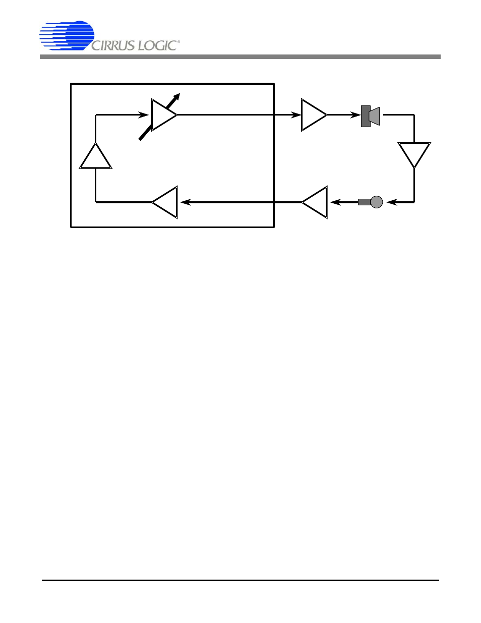
Physical law ensures that the system will howl at
the frequency of maximum coupling. Furthermore,
Speaker
Driver
Mic
Preamp
AO
CS6422
APO
TVol - Transmit
Volume
NSdt - Network
Sidetone
Air Coupling
Adjust RVol until howling begins; AC = 0 - RVo l - Mic -Spkr
0dB
-?dB
30dB
12dB
-12dB
RVol - Receive
Volume
+?dB
Adjust
D
isconn
ect
Ne
two
rk
Figure 11. Acoustic Coupling Measurement Method
Gain dB
(
)
30dB
RVol
3dB
Ч
(
)
–
=